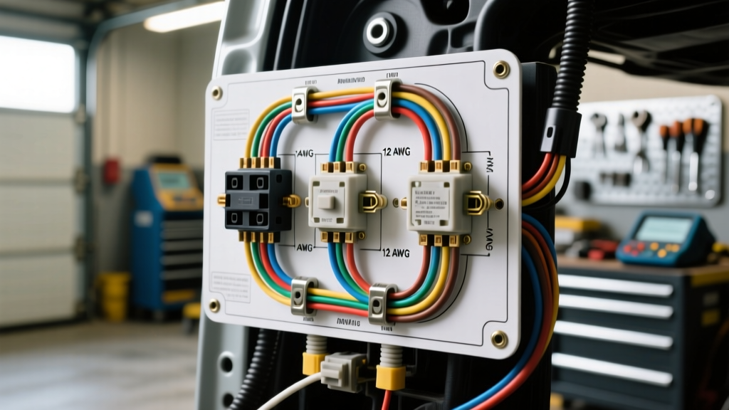
The Deceptive Simplicity of Single-Pole Automotive Switches
A Single Pole, Single Throw (SPST) switch is the most fundamental electrical control component in any vehicle. Whether you are wiring an aftermarket off-road LED light bar, an auxiliary fuel pump, a winch in-dash controller, or a simple cigarette lighter accessory socket, the SPST toggle or rocker switch is the standard interface. However, searching for a basic wiring diagram for a single pole switch often yields residential AC electrical schematics that are dangerously incorrect for 12V DC automotive applications.
In a vehicle, the chassis acts as the ground return path, and the environment is subjected to extreme vibration, heat, and moisture. Applying household wiring logic to an automotive harness is a leading cause of electrical fires, melted dashboards, and parasitic battery drains. This guide details the correct automotive relay-integrated diagram, outlines fatal wiring mistakes, and provides the exact AWG and terminal specifications required for a safe, SAE-compliant installation.
The Correct Automotive Wiring Diagram (Relay-Integrated)
A common and catastrophic mistake is wiring a high-draw accessory directly through the single pole switch. Dashboard-mounted SPST switches are typically rated for a maximum of 10A to 20A. If you wire a 30A light bar directly through the switch, the internal contacts will arc, overheat, and melt the plastic housing. The correct wiring diagram for a single pole switch in a vehicle always utilizes the switch to trigger an automotive relay (typically a standard 4-pin or 5-pin Bosch-style ISO mini relay, following DIN 72552 terminal standards).
The Standard 4-Pin Relay Circuit Path
- Power Source (Battery/Dist. Block): Fused 12V+ constant power routed to Relay Pin 30.
- Switch Feed: Fused 12V+ ignition-switched or constant power routed to the SPST Switch input terminal.
- Switch Output: 12V+ from the SPST Switch output terminal routed to Relay Pin 86 (Coil Positive).
- Relay Ground: Relay Pin 85 (Coil Negative) grounded to a clean, bare-metal chassis point.
- Load Feed: Relay Pin 87 (Normally Open) routed to the positive terminal of the accessory/load.
- Load Ground: Accessory negative terminal grounded directly to the chassis.
Critical Safety Warnings & Fatal Wiring Mistakes
Mistake 1: Switching the Ground Instead of the Power Feed
In residential wiring, switching the neutral line is a code violation but might still turn off a light bulb. In an automotive DC environment, switching the ground side of a load is a severe fire hazard. If you wire the single pole switch on the ground wire (between the accessory and the chassis), the entire positive wire harness from the battery to the accessory remains continuously energized (hot) at 12V, even when the switch is in the 'OFF' position. Because automotive wiring is routed through sheet metal bulkheads and along steel frames, any chafing or insulation failure on that 'hot' wire will result in a dead short to the chassis. If the main fuse is oversized or fails, this dead short will instantly ignite the wire harness. Always switch the positive power feed.
Mistake 2: Ignoring the SAE Fuse Proximity Rule
According to SAE J1128 standards and general automotive electrical best practices, a fuse only protects the wire downstream of it. A common error is running a long, unfused wire from the battery to the single pole switch on the dashboard, and placing the fuse near the switch. If the wire chafes against the steering column or firewall before reaching the switch, it will short to ground and cause a fire. The primary inline fuse must be installed within 18 inches of the power source (battery terminal or main distribution block), protecting the entire length of the wire running to the switch and relay.
Mistake 3: The Illuminated Switch Backfeed Trap
Many aftermarket SPST rocker switches feature an internal LED indicator. These switches often have three terminals: Power In, Power Out (to load/relay), and Ground (for the LED). A frequent mistake is wiring the LED ground terminal to the accessory load wire instead of a clean chassis ground. Because the accessory (like an LED light bar or fuel pump) has internal resistance and its own ground path, the 12V current will backfeed through the accessory's ground circuit, into the switch's LED ground terminal, and illuminate the dash switch dimly even when turned off. Worse, this backfeed can trigger sensitive ECU modules or cause parasitic battery drains. Always run a dedicated ground wire from the switch's LED terminal to a verified chassis ground.
Automotive Wire Gauge (AWG) and Fuse Sizing Matrix
Using undersized wire causes voltage drop, resulting in dim lights, slow motors, and melted insulation. The table below outlines the correct primary GXL (Cross-linked) wire sizing for 12V DC automotive circuits based on SAE standards. GXL wire is required for under-hood applications due to its thin insulation and high-temperature resistance (up to 125°C).
| Wire Gauge (AWG) | Max Continuous Amps | Recommended Fuse Size | Typical Automotive Application |
|---|---|---|---|
| 18 AWG | 5A - 7A | 5A | Switch trigger wires, relay coils, ECU sensors |
| 14 AWG | 15A | 15A | Fog lights, horn, interior accessory sockets |
| 12 AWG | 20A | 20A | Small LED light bars, auxiliary fuel pumps |
| 10 AWG | 30A | 30A | Off-road light bars, radiator fan motors |
| 8 AWG | 45A | 40A - 50A | Winch solenoids, high-amperage inverter feeds |
Connector and Terminal Selection
The vibration profile of a vehicle will quickly shake loose standard household wire nuts or poorly crimped spade terminals. When terminating your single pole switch and relay connections:
- Terminals: Use nylon-insulated, heat-shrink female disconnects for standard 1/4-inch switch spades. Ensure the wire gauge matches the terminal barrel (e.g., 16-14 AWG terminal for 14 AWG wire).
- Crimping: Use a ratcheting crimper (such as the IWISS IWS-3220M) to ensure a gas-tight mechanical and electrical bond. A proper crimp should withstand a 20-lb pull test without slipping.
- Splicing: Never use electrical tape for under-hood splices. The heat and oil will degrade the adhesive. Use adhesive-lined marine-grade heat shrink butt connectors to seal out moisture and prevent corrosion.
- Accessory Connection: For external accessories like light bars, use Deutsch DT series connectors with silicone seals to maintain an IP67 waterproof rating.
Troubleshooting Decision Tree: Switch Clicks but Accessory Fails
When your single pole switch actuates (or you hear the relay click) but the accessory does not power on, follow this diagnostic path using a digital multimeter (DMM):
- Test Load Voltage: Set DMM to DC Volts. Probe the accessory positive terminal and a known good chassis ground while the switch is ON.
- Result: 12V+ present. The wiring is correct; the accessory is internally faulty.
- Result: 0V or low voltage (e.g., 8V). Proceed to Step 2.
- Test Relay Output (Pin 87): Probe the wire leaving Relay Pin 87.
- Result: 12V+ present. You have an open circuit or broken wire between the relay and the accessory.
- Result: 0V. Proceed to Step 3.
- Test Relay Input (Pin 30): Probe the constant power wire entering the relay.
- Result: 0V. The main inline fuse is blown, or the battery feed wire is severed.
- Result: 12V+ present. The relay internal contacts are burnt or failed. Replace the relay.
Authoritative References
For further reading on automotive electrical standards and relay application guides, consult the following resources:
- SAE J1128: Low Tension Primary Cable Standard - Society of Automotive Engineers specifications for wire insulation and temperature ratings.
- Littelfuse Automotive Relay Application Guide - Technical data on DIN 72552 pinouts, contact materials, and inductive load suppression.
- Haynes Manuals: How to Wire a Relay - Practical automotive troubleshooting and step-by-step wiring tutorials for aftermarket accessories.