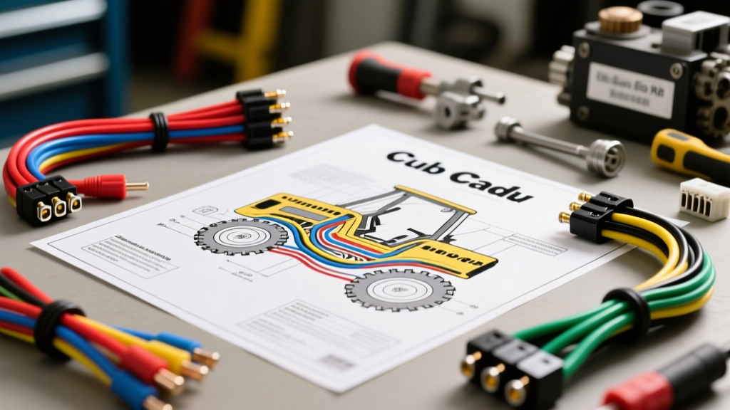
Navigating the Electrical Architecture of Cub Cadet Tractors
When diagnosing starting issues, PTO clutch failures, or charging system faults on MTD-manufactured lawn equipment, securing an accurate wiring diagram for a Cub Cadet tractor is the critical first step. Unlike older, purely mechanical small engines, modern Cub Cadet XT1 Enduro, XT2, and Z-Force zero-turn mowers rely on complex safety interlock modules, electromagnetic PTO clutches, and solid-state voltage regulators. Selecting the right schematic resource—and the corresponding replacement wiring products—requires an understanding of how these systems integrate. This product comparison and selection guide will help you choose the best diagram sources, harness replacement kits, and diagnostic tools for your specific Cub Cadet model.
Comparing Wiring Diagram Sources: OEM vs. Aftermarket
Not all schematics are created equal. When searching for a wiring diagram for a Cub Cadet, you will generally encounter three distinct product categories. Choosing the right one depends on whether you are performing a routine repair or executing a complete engine swap.
| Diagram Source Type | Best Use Case | Interlock Accuracy | Engine Specificity |
|---|---|---|---|
| OEM MTD Service Manuals | Dealership-level diagnostics, full harness replacement | Exact (Includes SAM relay logic) | High (Kohler/Kawasaki specific) |
| Aftermarket Repair Guides | Basic component testing, switch bypassing | Moderate (Often simplifies safety loops) | Low (Generic small engine blocks) |
| Parts Retailer Schematics | Identifying part numbers, tracing single circuits | High (Visual parts breakdowns) | Moderate (Model-year dependent) |
For professional or deep DIY repairs, OEM documentation is mandatory. The safety interlock system on a Cub Cadet XT2, for example, utilizes a series of normally-open (NO) and normally-closed (NC) microswitches tied to the seat, brake pedal, and PTO lever. Aftermarket guides frequently oversimplify these loops, leading to frustrating "no-crank" conditions after a repair. For verified OEM schematic breakdowns and exact harness part numbers, resources like eReplacementParts Cub Cadet OEM Schematics provide model-specific visual diagrams that map directly to MTD part numbers.
Harness Selection: OEM Assemblies vs. Custom Looms
Once your wiring diagram for a Cub Cadet has identified a shorted or degraded circuit, you must select a replacement strategy. You can either purchase a complete OEM harness assembly or build a custom loom using bulk automotive wire and connector kits.
Option A: Complete OEM Harness Assemblies
Buying an OEM MTD harness (such as part number 725-1741 for select XT1 models) guarantees that the wire lengths, firewall grommets, and factory tape wraps match the original equipment. This is the recommended route if the main chassis harness has become brittle due to UV exposure and engine bay heat cycling. However, OEM harnesses are expensive and often require significant disassembly of the steering column and dash to route properly.
Option B: Custom Looms and Pigtail Repair Kits
If the wiring diagram reveals that only the stator pigtail or the PTO clutch connector has melted—a very common failure point due to high amperage and vibration—building a custom repair harness is more cost-effective. This requires selecting the correct wire gauge and insulation type.
Wire Gauge and Insulation Specifications
When replicating circuits shown in your Cub Cadet wiring diagram, you must adhere to automotive and small engine electrical standards. The SAE J1128 Low Tension Primary Cable Standard dictates the requirements for wire insulation and current capacity in harsh environments. Never use standard THHN building wire; it lacks the chemical resistance to survive exposure to gasoline, oil, and ozone.
| Circuit Function | Standard OEM Wire Color | Required AWG Size | Recommended Insulation Type |
|---|---|---|---|
| Battery to Starter Solenoid | Red | 10 AWG or 8 AWG | SGX (Battery Cable) |
| PTO Electromagnetic Clutch | Purple / White Tracer | 14 AWG | GXL or TXL (Cross-linked) |
| Stator to Regulator/Rectifier | Yellow | 16 AWG | High-Temp PVC or Teflon |
| Safety Interlock Switches | Green / Black | 18 AWG | GXL (Thin-wall) |
| Chassis Ground Returns | Black | Match Positive Feed | GXL or SGX |
Expert Insight: The PTO clutch on most Cub Cadet Z-Force and XT series tractors draws between 3.5 and 5.0 amps continuously. While 16 AWG wire can technically handle this load, the factory diagrams specify 14 AWG to minimize voltage drop over the long routing distance from the dash relay to the front-mounted clutch. A voltage drop of more than 0.5V across the PTO circuit will cause the clutch to slip, overheat, and prematurely fail.
Engine-Specific Wiring: Kohler vs. Kawasaki
A major challenge when interpreting a wiring diagram for a Cub Cadet is accounting for the engine manufacturer. Cub Cadet utilizes both Kohler (Courage, Command, 7000 Series) and Kawasaki (FR, FS Series) engines, and their charging system wiring differs significantly.
- Kohler Stator Wiring: Typically utilizes a 3-wire stator output (Yellow, Yellow, Yellow) feeding into a combined Regulator/Rectifier. The center pin or separate wire (often Red or Purple) is the DC output to the battery, requiring a clean 12V+ reference to function.
- Kawasaki Stator Wiring: Often employs a separate lighting coil (White wire) for auxiliary accessories and a distinct charging coil. Misinterpreting these pins when swapping engines will result in blown fuses or a dead battery.
Always verify the engine specification number (e.g., Kohler PA-CH740) against the schematic. The tractor chassis diagram will only show the harness up to the engine firewall plug; the engine-specific diagram is required for the stator and ignition module pinouts.
Connector Selection: Weather-Pack vs. Superseal
When your diagram leads you to a corroded connection, selecting the right replacement connector kit is vital for long-term reliability. The two industry standards for small engine and automotive wiring are Delphi Weather-Pack and AMP Superseal.
Delphi Weather-Pack (Recommended for Cub Cadet)
Most MTD-manufactured tractors use Delphi Automotive Connector Systems, specifically the Weather-Pack series. These connectors feature cylindrical pins and sockets with individual silicone rubber seals. They are ideal for the high-vibration, high-moisture environment under a tractor hood. When repairing a PTO clutch pigtail, always use a dedicated Weather-Pack ratcheting crimper to ensure the wire and insulation crimps are perfectly formed, preventing moisture ingress that leads to green copper corrosion.
AMP Superseal 1.5
While superior for high-density ECU connections, Superseal connectors are rarely used on standard Cub Cadet chassis harnesses. Avoid mixing connector types on a single loom, as it complicates future diagnostics and requires carrying multiple crimp tool profiles.
Diagnostic Tools for Schematic Verification
Having the correct wiring diagram for a Cub Cadet is only half the battle; you must verify the schematic against the physical tractor. We recommend the following tool selection based on your diagnostic needs:
- Digital Multimeter (DMM): Essential for measuring stator AC output (should be 28-35V AC at 3600 RPM) and testing PTO clutch coil resistance (typically 2.5 to 4.5 ohms).
- Power Probe / Circuit Tester: Ideal for quickly verifying 12V presence at the ignition switch terminals and safety interlock relays without back-probing and damaging delicate Weather-Pack seals.
- Voltage Drop Test Leads: Use these to measure the voltage differential across the main 30A fuse and the PTO relay contacts while the circuit is under load. A reading above 0.2V indicates internal corrosion not visible on the wiring diagram.
Final Selection Strategy
To successfully repair your tractor's electrical system, start by obtaining the exact OEM MTD wiring diagram for your specific Cub Cadet model and serial number range. Use this schematic to identify the failing circuit, then source GXL or TXL wire matching the factory AWG and color codes. By pairing accurate OEM diagrams with SAE-compliant wiring products and proper Weather-Pack terminations, you will restore your tractor's electrical system to factory reliability, ensuring the safety interlocks function correctly and the charging system maintains optimal voltage during heavy mowing conditions.