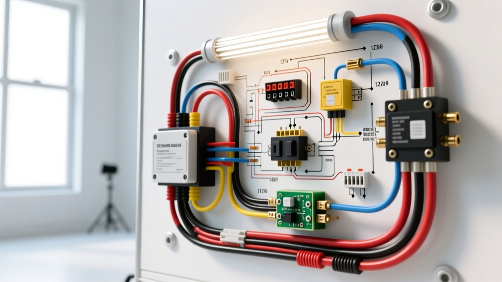
Introduction to 12V DC Fluorescent Lighting in Custom Vehicle Builds
While modern camper vans and utility trucks have largely transitioned to LED arrays, 12V DC fluorescent lighting remains a staple in vintage Airstream restorations, custom utility bed builds, and heavy-duty off-grid RVs. Upgrading or restoring these fixtures requires a deep understanding of high-frequency electronic ballasts. Unlike standard 120V AC magnetic ballasts found in residential applications, a 12V DC electronic ballast acts as a solid-state inverter, stepping up 12V DC to over 600V peak-to-peak at high frequencies (20kHz to 50kHz) to strike the argon-mercury gas mixture inside the tube.
When drafting your custom wiring diagram, fluorescent light ballast components require specific attention to inrush current, voltage drop, and RVIA (Recreational Vehicle Industry Association) color codes. A poorly designed circuit will result in flickering tubes, melted OEM wall switches, or premature ballast failure. This guide provides the exact technical specifications, relay modification schematics, and AWG sizing charts required to execute a flawless 12V fluorescent lighting upgrade in your vehicle.
The Anatomy of a 12V DC Electronic Ballast
Standard 12V DC fluorescent ballasts (such as the Fulham WorkHorse or Philips OEM RV series) typically feature a 4-pin or 6-pin output harness designed to drive one or two T5/T8 tubes. The input side requires a clean, stable 12V DC source. Because the internal oscillator draws a significant surge of current during the 1-to-3 second ignition phase, the upstream wiring and overcurrent protection must be rated for inductive loads, not just continuous resistive loads.
Failing to account for the starting voltage and inrush current is the most common mistake in aftermarket camper builds. If the voltage at the ballast input terminals drops below 10.5V during the strike phase, the ballast's internal protection circuit will trigger a lockout, resulting in a flashing or dead tube.
RVIA Wiring Standards and Color Codes
Automotive SAE standards and RVIA standards differ significantly in their DC color coding. To maintain safety and serviceability, your vehicle wiring diagram fluorescent light ballast circuit must adhere to RVIA guidelines for 12V DC systems:
- 12V+ (Positive): Yellow (Primary) or Red (Secondary/Auxiliary)
- 12V- (Ground): White
- Switched Trigger Wire: Blue or Light Blue
Never use black for 12V+ in an RV or camper build, as black is strictly reserved for 120V AC hot wires in RVIA-compliant motorhomes and travel trailers. Mixing these standards can lead to catastrophic short circuits during future servicing.
Wiring Diagram: Fluorescent Light Ballast with ISO Relay Mod
OEM RV rocker switches are typically rated for 5A to 10A continuous. A dual-lamp 12V DC fluorescent ballast can draw 3.5A continuous, but the inrush can spike to 8A-12A. Running multiple ballasts through a single OEM switch will cause the internal copper contacts to arc, melt, and fail. The professional modification requires integrating a Bosch-style 5-pin ISO Mini Relay to handle the heavy inductive load.
Component & Pinout Reference Table
| Relay Terminal | Function | Wire Color (RVIA) | Connection Point | AWG Size |
|---|---|---|---|---|
| 30 | Constant 12V+ Load Input | Yellow | DC Distribution Bus Bar (Fused) | 12 AWG |
| 87 | Switched 12V+ Load Output | Yellow | Ballast Red Input Wire | 12 AWG |
| 86 | 12V+ Coil Trigger | Blue | OEM Wall Switch Output | 16 AWG |
| 85 | Coil Ground | White | Vehicle Chassis / Ground Bus | 16 AWG |
| 87a | Normally Closed (Unused) | N/A | Cut and heat-shrink sealed | N/A |
Wire Sizing and Voltage Drop Calculations
Voltage drop is the enemy of 12V DC fluorescent lighting. According to SAE J1128 standards for low-tension primary cable, wire resistance increases exponentially with temperature and length. For a 30-foot one-way run (60-foot round trip) from the DC fuse panel to the ceiling-mounted ballast, standard 14 AWG wire will experience a voltage drop that can prevent the tube from striking.
AWG Sizing Chart for 12V DC Ballasts (60ft Round Trip)
| Total Ballast Wattage | Continuous Draw (A) | Recommended AWG | Fuse Rating (Time-Delay) | Max Voltage Drop |
|---|---|---|---|---|
| 15W (Single T8) | 1.4A | 16 AWG | 3A Mini-ATC | 0.41V (3.4%) |
| 30W (Dual T8) | 2.8A | 14 AWG | 5A Mini-ATC | 0.48V (4.0%) |
| 40W+ (Dual HO T5) | 4.5A+ | 12 AWG | 7.5A Mini-ATC | 0.36V (3.0%) |
Note: Always use Time-Delay (Slow-Blow) fuses for fluorescent ballast circuits. Standard fast-acting fuses will nuisance-blow during the cold-cathode ignition phase. Refer to Littelfuse automotive fuse specifications for time-current curves.
Step-by-Step Installation and Crimping Specifications
Proper termination is critical in high-vibration vehicle environments. The high-frequency output of the ballast can cause skin-effect heating at poor crimp joints.
- Strip and Crimp: Strip 5/16 inch of insulation from the 12 AWG Yellow wire. Use a ratcheting crimper calibrated for 12 AWG non-insulated ring terminals. The crimp must withstand a 20 lb pull-test.
- Seal the Joint: Slide 3:1 ratio adhesive-lined marine heat shrink over the terminal. Apply heat until the internal sealant purges slightly from the edges, ensuring complete moisture and vibration protection.
- Bus Bar Torque: When terminating the ground and positive wires at the DC distribution bus bar, torque the 1/4-20 UNC stainless steel nuts to exactly 45-55 in-lbs. Under-torquing leads to arcing; over-torquing strips the soft copper bus material.
- Dielectric Grease: Apply a thin layer of dielectric grease to the 4-pin output connector before mating it to the fluorescent tube pins to prevent galvanic corrosion, a common issue in high-humidity camper environments.
Troubleshooting Common Ballast and Tube Failure Modes
Even with a perfect wiring diagram, fluorescent light ballast circuits can exhibit specific failure modes. Use this diagnostic tree to isolate the issue:
- Symptom: Tube flashes repeatedly but never stays lit.
Cause: Voltage drop during the strike phase or a failing tube cathode.
Fix: Measure voltage at the ballast input terminals while the switch is engaged. If it drops below 11.0V, upgrade the wire gauge or clean the DC bus bar connections. If voltage is stable, replace the fluorescent tube. - Symptom: Ballast hums loudly and tube glows only at the ends.
Cause: The ballast is failing to step up the frequency, often due to a blown internal MOSFET or a shorted output winding.
Fix: Disconnect the output harness. If the hum persists with no load, replace the ballast. Always check for pinched output wires touching the metal chassis. - Symptom: OEM Wall switch feels hot to the touch.
Cause: The switch is carrying the full inductive load of the ballast without a relay.
Fix: Immediately disconnect power. Rewire the circuit using the ISO Relay Mod detailed above to limit the switch load to the 150mA coil draw.
Authoritative References & Compliance
All wiring modifications detailed in this guide comply with the RVIA (Recreational Vehicle Industry Association) electrical guidelines for low-voltage DC systems, as well as SAE J1128 standards for automotive primary cable. Always verify your specific vehicle's chassis grounding points and ensure your DC-DC charger or solar charge controller can handle the transient inrush loads of multiple fluorescent ballasts engaging simultaneously.