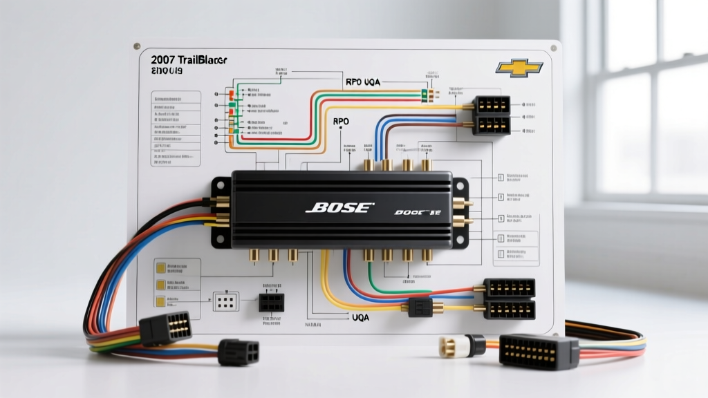
GMT360 Platform Audio Architecture (RPO UQA)
The 2007 Chevrolet TrailBlazer, built on the GMT360 platform, features an optional Bose Premium Audio System identified by RPO code UQA. Unlike base audio systems where the head unit contains the internal amplification, the UQA system relies on a dedicated external amplifier to drive the cabin speakers and the rear-mounted subwoofer. Understanding the 2007 Chevy TrailBlazer Bose amp wiring diagram is critical for diagnosing audio failures, bypassing the factory amplifier for aftermarket head unit installations, or repairing damaged harnesses. The factory head unit outputs low-level (line-level) balanced audio signals to the amplifier, which then amplifies the signal to high-level outputs for the door and rear pillar speakers. This architecture means that simply swapping the head unit without addressing the amplifier will result in severe audio distortion or complete system failure.
Physical Access and Connector Identification
Before testing circuits or attempting a bypass, you must physically access the amplifier. In the 2007 TrailBlazer, the Bose amplifier is mounted in the rear left quarter panel, behind the cargo area trim. To access it, remove the rear cargo threshold plate (using a trim removal tool to pop the plastic push-pins), followed by the rear left quarter panel trim piece. The amplifier is secured to a metal bracket using three 10mm hex bolts. Once unbolted, you will find three main harness connectors mated to the unit: a 16-way Metri-Pack 280 connector for power and data (C1), and two 24-way connectors for audio inputs (C2) and speaker outputs (C3). Always disconnect the negative battery terminal before unseating these connectors to prevent shorting the Class 2 data bus or blowing the 20A radio fuse in the rear fuse block.
2007 Chevy TrailBlazer Bose Amp Wiring Diagram & Pinouts
The following tables detail the exact pin configurations, OEM wire colors, and circuit functions for the RPO UQA amplifier. These specifications are derived from GM service documentation and are essential for multimeter testing and continuity checks.
Connector C1: Power, Ground, and Serial Data (16-Way)
| Pin | Wire Color | AWG | Circuit Name / Function |
|---|---|---|---|
| A1 | Orange | 14 | Battery Positive Voltage (Constant 12V+) |
| A2 | Black/White | 14 | Main Ground (Chassis) |
| A8 | Dark Green | 20 | Class 2 Serial Data Bus |
| A9 | Yellow | 18 | Ignition Positive Voltage (Switched 12V+) |
| A12 | Brown/White | 20 | Amplifier Enable / Turn-On Signal |
Connector C2: Low-Level Audio Inputs from Head Unit (24-Way)
| Pin | Wire Color | Channel | Signal Type |
|---|---|---|---|
| B1 | Light Green | Left Front (+) | Low-Level Balanced |
| B2 | Light Green/Black | Left Front (-) | Low-Level Balanced |
| B3 | Dark Green | Right Front (+) | Low-Level Balanced |
| B4 | Dark Green/Black | Right Front (-) | Low-Level Balanced |
| B9 | Light Blue | Left Rear (+) | Low-Level Balanced |
| B10 | Light Blue/Black | Left Rear (-) | Low-Level Balanced |
| B11 | Dark Blue | Right Rear (+) | Low-Level Balanced |
| B12 | Dark Blue/Black | Right Rear (-) | Low-Level Balanced |
Connector C3: High-Level Speaker Outputs (24-Way)
| Pin | Wire Color | Destination | AWG |
|---|---|---|---|
| C1 | Tan | Left Front Speaker (+) | 18 |
| C2 | Gray | Left Front Speaker (-) | 18 |
| C3 | Light Green | Right Front Speaker (+) | 18 |
| C4 | Dark Green | Right Front Speaker (-) | 18 |
| C9 | Brown | Left Rear Speaker (+) | 18 |
| C10 | Yellow | Left Rear Speaker (-) | 18 |
| C11 | Dark Blue | Right Rear Speaker (+) | 18 |
| C12 | Light Blue | Right Rear Speaker (-) | 18 |
| C15 | Purple | Subwoofer (+) | 16 |
| C16 | Purple/Black | Subwoofer (-) | 16 |
Class 2 Serial Data Bus Integration
A unique aspect of the 2007 Chevy TrailBlazer Bose amp wiring diagram is the inclusion of the Class 2 Serial Data line (Dark Green, Pin A8). According to the SAE J1850 standard, which governs GM's Class 2 communication protocol, this single wire operates at 10.4 kbps and allows the amplifier to communicate with the Body Control Module (BCM) and the head unit. The amplifier uses this bus to receive volume-dependent equalization data, speed-compensated volume adjustments, and diagnostic trouble codes (DTCs). If the Dark Green wire is severed, shorted to ground, or suffers from high resistance due to corrosion, the amplifier may enter a protective 'sleep' mode, resulting in zero audio output even if the power and ground circuits are perfectly intact. When diagnosing a dead amplifier, always verify that the Class 2 line pulses between 0V and 7V using a digital multimeter set to DC voltage while the ignition is in the 'RUN' position.
Diagnostic Decision Tree: Common Bose Amplifier Failures
Automotive electrical experts frequently encounter specific failure modes on the GMT360 platform. Use this symptom-cause-fix decision tree to isolate the root of your audio issue.
- Symptom: Complete audio loss; radio display functions normally but no sound from any speaker.
Cause: Loss of constant 12V+ (Orange wire) or blown 20A 'Radio/Amp' fuse in the rear seat fuse block.
Fix: Test Pin A1 on Connector C1 for battery voltage. If missing, check the rear fuse block and inspect the inline fusible link near the battery. - Symptom: Audio cuts out intermittently when driving over bumps or during high-humidity conditions.
Cause: Class 2 Data Bus (Dark Green) shorting against the chassis or suffering from terminal fretting corrosion.
Fix: Inspect Pin A8. Apply dielectric grease to the Metri-Pack terminal and ensure the wire has adequate slack to prevent tension on the connector head. - Symptom: Severe distortion from the rear left quarter panel, followed by complete subwoofer failure.
Cause: Water intrusion. The GMT360 SUVs are notorious for rear quarter panel seam sealer failure and degraded liftgate weatherstripping, allowing water to pool directly onto the C3 connector.
Fix: Remove the amplifier, inspect C3 for green/white galvanic corrosion. Clean terminals with electrical contact cleaner, reseal the exterior quarter panel seams with 3M Body Panel Sealant, and replace the amplifier if the internal PCB is compromised.
Wire Repair and AWG Specifications
When repairing damaged wires on the Bose amplifier harness, maintaining the correct American Wire Gauge (AWG) is non-negotiable. The main power and ground circuits (Orange and Black/White) utilize 14 AWG wire to handle the high current draw of the amplifier's internal switching power supply and Class D output stages. Splicing in 18 AWG wire for these circuits will cause a severe voltage drop under heavy bass loads, triggering the amplifier's internal low-voltage protection circuit and causing the audio to cut out. Always use adhesive-lined marine-grade heat shrink for any soldered connections in the rear cargo area to prevent moisture ingress. For the low-level audio inputs on Connector C2, ensure that the twisted-pair configuration is maintained. Untwisting these balanced audio wires will introduce alternator whine and electromagnetic interference (EMI) from the vehicle's CAN-bus and ignition systems. For deeper diagnostic procedures and factory schematic references, technicians often consult Haynes GM Full-Size SUV repair manuals or dedicated community archives like GM Truck Club for real-world GMT360 teardowns and bypass harness configurations.