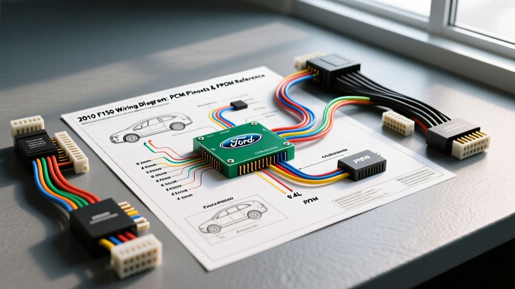
2010 Ford F-150 Electrical Architecture Overview
The 2010 Ford F-150 represents a critical year in the 12th-generation lineup, featuring a highly multiplexed electrical architecture designed to manage everything from the Powertrain Control Module (PCM) to the Supplemental Restraint System (SRS). For automotive technicians and DIY enthusiasts, navigating the 2010 F150 wiring diagram requires an understanding of Ford's specific wire color coding, CAN bus network topologies, and pulse-width modulated (PWM) accessory controls. This technical specification reference focuses primarily on the 5.4L 3-Valve (3V) V8 engine, detailing the PCM pinouts, the notorious Fuel Pump Driver Module (FPDM) circuit, and Variable Cam Timing (VCT) solenoid diagnostics.
Powertrain Control Module (PCM) Pinout Specifications
The 2010 F-150 5.4L utilizes a sophisticated PCM mounted in the engine bay, connected via three primary harness connectors: C1381A, C1381B, and C1381C. Accurate diagnostics require probing the correct cavities without back-probing and risking terminal spread. Below is a critical reference for Connector C1381B (64-pin), which houses the primary 5-volt reference circuits, signal returns, and throttle position sensor (TPS) wiring.
PCM Connector C1381B (Selected Sensor & Reference Pins)
| Pin | Circuit Function | Wire Color (OEM) | AWG | Voltage / Spec |
|---|---|---|---|---|
| 3 | VREF (5V Reference) | Brown/White (BN/WH) | 20 | 4.8V - 5.2V |
| 5 | Signal Return (SIG RTN) | Gray/Red (GY/RD) | 20 | < 0.05V (to Chassis Ground) |
| 24 | Throttle Position Sensor 1 | Yellow/White (YE/WH) | 22 | 0.5V - 4.5V (Sweep) |
| 37 | Throttle Position Sensor 2 | Violet/Gray (VT/GY) | 22 | 4.5V - 0.5V (Inverse Sweep) |
| 43 | Mass Air Flow (MAF) Signal | White/Light Blue (WH/LB) | 22 | 0.7V (Idle) - 4.2V (WOT) |
| 57 | Power Ground (PCM Logic) | Black (BK) | 12 | Continuity to Battery (-) |
Expert Note: When diagnosing a P0122 or P0222 (Throttle Position Sensor Circuit Low), always verify the integrity of Pin 3 (VREF). A short to ground on the BN/WH wire anywhere in the engine bay harness will pull the entire 5V reference network down, causing cascading failures across the MAP, TPS, and EGR sensors.
Fuel Pump Driver Module (FPDM) Wiring & Failure Modes
Unlike older vehicles that utilize a simple 12V relay to power the fuel pump, the 2010 F-150 uses a Fuel Pump Driver Module (FPDM) to control pump speed via a Pulse Width Modulated (PWM) signal. This reduces fuel vaporization and extends pump life. However, the FPDM is the subject of widespread failure due to galvanic corrosion.
FPDM Location and Corrosion TSB
The FPDM is located in the rear of the vehicle, near the spare tire. Ford originally mounted this module to an aluminum bracket. The dissimilar metals (aluminum bracket and steel chassis) combined with road salt and moisture create a galvanic battery effect, leading to severe corrosion that eats through the module's casing and destroys the internal PCB. Ford issued multiple Technical Service Bulletins (TSBs) addressing this, eventually revising the part to include a plastic isolation barrier. For deeper historical context on these failures, refer to the NHTSA Technical Service Bulletins database.
FPDM Pinout and Circuit Specifications
| Pin | Function | Wire Color | AWG | Diagnostic Value |
|---|---|---|---|---|
| 1 | Fuel Pump Control (PWM from PCM) | White (WH) | 18 | 15% - 85% Duty Cycle |
| 2 | Fuel Pump Monitor (Feedback to PCM) | Gray/Orange (GY/OG) | 20 | Inverse Duty Cycle of Pin 1 |
| 3 | Chassis Ground | Black (BK) | 12 | < 0.1 Ohms to Battery (-) |
| 4 | Module Power (from BJB) | Pink/Light Blue (PK/LB) | 12 | Battery Voltage (Hot at all times) |
| 5 | Fuel Pump Power Output | White (WH) | 14 | PWM 12V to Fuel Pump |
| 6 | Fuel Pump Ground Output | Black (BK) | 14 | Return path through module |
Testing the PWM Signal: A standard digital multimeter (DMM) will only show an average voltage (typically 5V-7V) on the White (WH) command wire. To properly diagnose a P1233 (Fuel System Disabled or Offline) or P1237, you must use an oscilloscope or a DMM with a duty cycle function. At idle, the PCM commands a lower duty cycle (approx. 30-40%). Under heavy load or WOT, the duty cycle increases to 70-85%. If the scope shows a flat 12V line, the FPDM has failed internally and is defaulting to full battery voltage to keep the vehicle running in limp mode.
Variable Cam Timing (VCT) Solenoid Circuit
The 5.4L 3V engine relies on VCT solenoids to advance and retard camshaft timing using engine oil pressure. Electrically, these solenoids are grounded by the PCM to actuate. Oil contamination and sludge are common mechanical failure points, but electrical harness degradation in the valve cover grommets is equally prevalent.
- Bank 1 (Passenger Side) VCT Solenoid:
- VPWR (Voltage Power): Red/Light Green (RD/LG) - 18 AWG
- PCM Control Ground: Yellow/Black (YE/BK) - 20 AWG
- Bank 2 (Driver Side) VCT Solenoid:
- VPWR (Voltage Power): Red/Light Green (RD/LG) - 18 AWG
- PCM Control Ground: White/Black (WH/BK) - 20 AWG
Specification: The internal resistance of a healthy 2010 F-150 VCT solenoid should measure between 6.0 and 13.0 ohms at 68°F (20°C). If your multimeter reads OL (open) or below 4 ohms (shorted), the solenoid coil has failed. Always inspect the 14-pin valve cover connector for oil ingress, which causes capillary action to wick oil into the main engine harness.
Data Link Connector (DLC) & CAN Bus Topology
When plugging in an advanced bi-directional scan tool, understanding the 2010 F-150 OBD-II DLC pinout is vital for network communication diagnostics. Ford utilizes a dual-bus system for this model year.
| DLC Pin | Network | Wire Color | Termination Resistance |
|---|---|---|---|
| 6 | HS-CAN (+) | White/Blue (WH/BU) | 60 Ohms (across Pins 6 & 14) |
| 14 | HS-CAN (-) | White (WH) | 60 Ohms (across Pins 6 & 14) |
| 3 | MS-CAN (+) | White/Green (WH/GN) | 60 Ohms (across Pins 3 & 11) |
| 11 | MS-CAN (-) | White/Violet (WH/VT) | 60 Ohms (across Pins 3 & 11) |
| 16 | Battery Positive | Light Green/Purple (LG/VT) | N/A (Fused 12V) |
The High-Speed CAN (HS-CAN) operates at 500 kbps and handles powertrain modules (PCM, TCM, ABS). The Medium-Speed CAN (MS-CAN) operates at 125 kbps and handles body control modules (BCM, IPC, HVAC). For comprehensive network standards, consult the SAE International CAN bus documentation.
Diagnostic Troubleshooting Decision Tree
Use this structured decision tree to isolate common 2010 F-150 electrical faults without throwing unnecessary parts at the vehicle.
Symptom: Engine Cranks But Will Not Start (Fuel Pump Inaudible)
- Check Inertia Fuel Shutoff (IFS) Switch: Located behind the passenger side kick panel. Verify continuity. If tripped, reset and retest.
- Verify FPDM Power: Probe the PK/LB wire at the FPDM. If 0V, check Fuse 19 (20A) in the Battery Junction Box (BJB).
- Inspect FPDM Physical Condition: Remove the module from the spare tire area. If the aluminum bracket is corroded and the casing is compromised, replace the FPDM and install the revised plastic isolation bracket.
- Verify PWM Command: Use an oscilloscope on the WH wire (Pin 1). If the PCM is sending a 30-50% duty cycle but the pump receives no power, the FPDM internal MOSFETs are destroyed.
Symptom: P0443 (EVAP Purge Control Valve Circuit Malfunction)
- Locate Purge Valve: Mounted on the intake manifold near the firewall.
- Test Valve Resistance: Disconnect the 2-pin connector. Measure across the valve terminals. Spec: 26-34 ohms. Replace if out of spec.
- Check Harness for Chafing: The EVAP harness routes near the EGR tube. Inspect the VPWR (RD/LG) and PCM control (YE/BK) wires for heat damage and melted insulation causing a short to ground.
- Verify PCM Driver: Connect a test light between B+ and the control wire. Command the EVAP solenoid ON via a bi-directional scan tool. The test light should illuminate. If not, and the harness is confirmed good, the PCM internal driver has failed.
Authoritative References & Further Reading
For complete, factory-authorized schematics and connector cavity views, technicians should always cross-reference their findings with official documentation. The wiring diagrams provided in this guide are synthesized for diagnostic reference, but physical wire colors may vary slightly based on the specific build plant and production month.
- Ford Motorcraft Service Manuals - Official repository for OEM wiring diagrams, TSBs, and pinpoint test procedures.
- SAE International - Standards for Controller Area Network (CAN) topology and multiplexed signal diagnostics.
- National Highway Traffic Safety Administration (NHTSA) - Database for safety recalls and manufacturer service bulletins regarding electrical fire hazards and FPDM failures.
Disclaimer: Always disconnect the negative battery terminal before probing or repairing high-current circuits. Use high-impedance digital multimeters and proper T-pin back-probes to prevent terminal damage in weather-pack connectors.