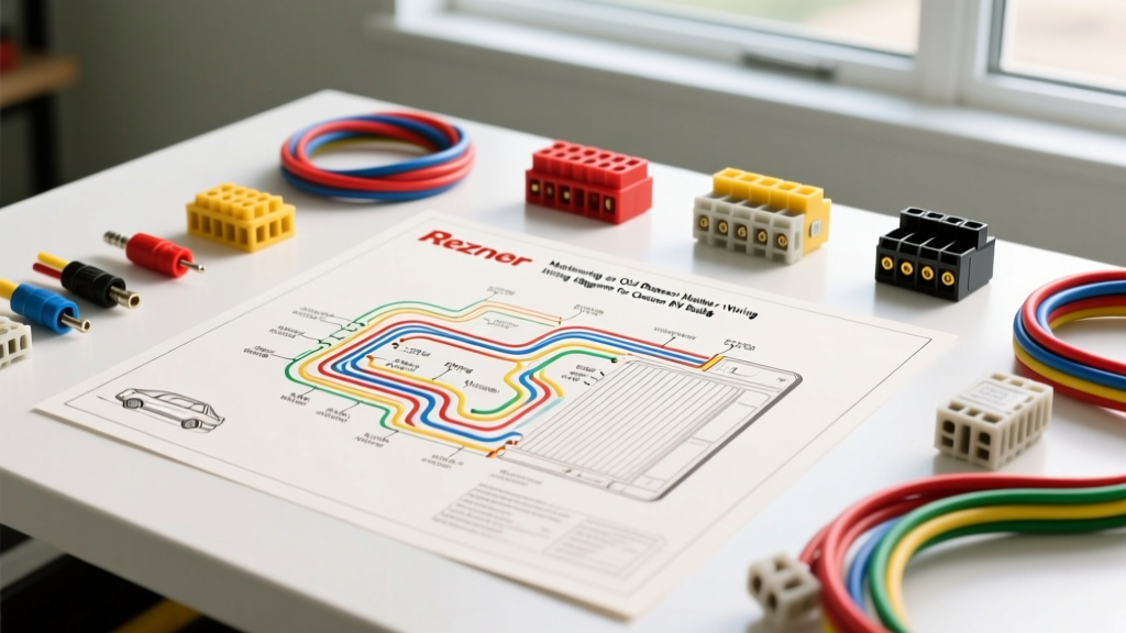
Introduction to Mobile HVAC Integration
When building custom expedition trucks, mobile command centers, or large skoolie RV conversions, standard 12V DC furnaces often fall short of the BTU output required to heat a massive insulated cargo bay or living space. This leads many advanced DIYers and mobile mechanics to repurpose commercial-grade unit heaters. If you are searching for an old reznor heater wiring diagram, you are likely dealing with a legacy V3, UDAP, or similar Reznor gas-fired unit heater. While these units were originally designed for static garage and warehouse installations, their robust cast-iron or heavy-gauge steel heat exchangers and simple 24VAC control circuits make them excellent candidates for mobile retrofitting.
However, adapting a 120V AC commercial heater into a 12V DC vehicle environment requires a deep understanding of electrical fundamentals. You cannot simply wire a commercial thermostat to a vehicle battery. This guide breaks down the beginner-friendly fundamentals of reading the schematic, adapting the power supply, and safely integrating the control circuit into a high-vibration mobile environment.
Decoding the Old Reznor Heater Wiring Diagram
Older Reznor schematics can look intimidating to beginners because they map out both the high-voltage (120VAC) power circuit and the low-voltage (24VAC) control circuit on the same page. To master the diagram, you must learn to separate these two distinct systems.
1. The 120VAC Power Circuit
The primary power circuit supplies electricity to the blower motor and the primary side of the step-down transformer. In an older Reznor unit, you will typically find a Permanent Split Capacitor (PSC) blower motor rated between 1/4 HP and 1/2 HP. This motor requires a standard 120VAC supply, drawing anywhere from 3A to 6A during operation. The schematic will show the hot (black), neutral (white), and ground (green/bare) lines feeding into a junction box, passing through a manual reset limit switch or a service disconnect, and terminating at the motor and transformer.
2. The 24VAC Control Circuit
The control circuit is the 'brain' of the heater. A 40VA (Volt-Ampere) step-down transformer converts 120VAC to 24VAC. This low-voltage side powers the thermostat, the gas valve solenoid, and the safety limit switches. According to standard Reznor Technical Manuals, the 24V circuit relies on a series of normally-closed (NC) safety switches. If the unit overheats, the high-limit switch opens, breaking the 24V circuit and shutting down the gas valve immediately.
Adapting 120V AC to a 12V DC Vehicle System
Because your vehicle runs on a 12V or 24V DC battery bank, you must introduce a Pure Sine Wave Inverter to power the Reznor unit. Modified sine wave inverters will cause the PSC blower motor to overheat, buzz loudly, and eventually fail due to harmonic distortion.
Sizing the Inverter and Battery Wiring
A 1/2 HP blower motor consumes roughly 370 watts while running. However, electric motors experience a massive current spike upon startup, known as Locked Rotor Amps (LRA). The LRA can be four to six times the running wattage. Therefore, a 1500W to 2000W Pure Sine Wave inverter is mandatory to handle the startup surge without triggering the inverter's low-voltage cutoff.
To wire the inverter to your vehicle's battery bank, you must use heavy-gauge stranded copper wire to prevent voltage drop. Following SAE J1128 guidelines for low-tension primary cable and standard DC voltage drop charts, use the following AWG sizing for inverter runs:
- Under 5 feet: 1/0 AWG or 2/0 AWG stranded tinned copper.
- 5 to 10 feet: 2/0 AWG or 3/0 AWG.
- Over 10 feet: 4/0 AWG (Highly recommended to keep inverter runs as short as possible).
Always install a Class T fuse or ANL fuse on the positive inverter cable within 18 inches of the battery terminal to protect against catastrophic short circuits.
Control Circuit Pinout and Relay Integration
When wiring the thermostat and safety switches in a mobile application, you must adhere to standard HVAC color codes to ensure future serviceability. While 18 AWG solid thermostat wire is standard in residential homes, the constant vibration of a vehicle will cause solid wire to fatigue and snap. Always use 16 AWG stranded marine-grade wire for all 24VAC control wiring in an RV or truck build.
| Terminal / Function | Standard Wire Color | AWG Size (Mobile) | Description & Mobile Integration Notes |
|---|---|---|---|
| R (Power) | Red | 16 AWG Stranded | 24VAC Hot from transformer secondary. Connects to thermostat R terminal. |
| W (Heat) | White | 16 AWG Stranded | Heat call. Routes through high-limit and rollout switches before terminating at the gas valve solenoid. |
| G (Fan) | Green | 16 AWG Stranded | Controls the blower relay. In mobile setups, wire this to a manual override switch for 'Fan Only' ventilation. |
| C (Common) | Blue or Brown | 16 AWG Stranded | 24VAC Common. Completes the circuit back to the transformer. Do not bond to vehicle chassis ground. |
| High Limit Switch | N/A (In Series) | 16 AWG Stranded | Normally Closed (NC). Automatically resets when temperature drops below safe threshold. |
| Rollout Switch | N/A (In Series) | 16 AWG Stranded | Normally Closed (NC). Manual reset required. Trips if flame rolls out of the burner box. |
Safety, Grounding, and Vibration-Proofing
One of the most critical mistakes beginners make when reading an old Reznor heater wiring diagram and applying it to a vehicle is misunderstanding grounding. In a static building, the neutral and ground are bonded at the main service panel. In a vehicle, bonding the AC neutral to the DC chassis ground can cause stray currents, galvanic corrosion, and severe shock hazards, especially if the vehicle is plugged into shore power.
Isolated Grounding for Mobile Units
Your Pure Sine Wave inverter should have an internal neutral-to-ground bond (or a bonding plug if required by the inverter manufacturer). The Reznor heater's 120VAC green ground wire must be tied directly to the inverter's AC ground terminal or a dedicated AC grounding bus bar that is isolated from the vehicle's 12V DC chassis. Furthermore, the 24VAC 'C' (Common) wire from the transformer must never be grounded to the vehicle chassis. The 24V control circuit must remain a floating, isolated system.
Vibration-Proofing Connections
Wire nuts are strictly prohibited in mobile environments. The constant harmonic vibration from diesel engines and road travel will vibrate wire nuts loose, leading to arcing and fires. For all 120VAC and 24VAC connections:
- Use adhesive-lined marine-grade heat shrink terminals.
- Crimp all connections using a calibrated ratchet crimper to ensure a gas-tight mechanical bond.
- Secure all wiring looms with P-clamps and rubber isolation grommets every 12 inches to prevent chafing against the Reznor's sheet metal housing.
For comprehensive safety standards regarding mobile HVAC and electrical installations, always refer to NFPA 1192 (Standard on Recreational Vehicles), which outlines strict requirements for overcurrent protection and wire routing in mobile applications.
Troubleshooting Common Mobile Failures
When your repurposed Reznor unit fails to operate, use this symptom-cause-fix decision tree to diagnose the issue without blindly replacing parts.
Symptom 1: Blower Motor Hums but Will Not Spin
- Cause: Voltage drop at the inverter during motor startup, or a failing run capacitor.
- Fix: Measure the AC voltage at the motor terminals while the thermostat calls for heat. If the voltage drops below 105VAC, your inverter is undersized for the LRA surge, or your DC battery cables are too thin (voltage drop on the DC side is starving the inverter). Upgrade to 2/0 AWG battery cables and verify the run capacitor's microfarad rating.
Symptom 2: Unit Short Cycles (Ignites, then Shuts Down After 3 Seconds)
- Cause: The flame sensor is not detecting a flame, or the high-limit switch is tripping prematurely due to poor airflow.
- Fix: Check the ducting in your RV or truck bay. If the Reznor unit is mounted in a tight enclosure without adequate return air, the heat exchanger will overheat instantly, tripping the limit switch. Ensure at least 20% more return air volume than discharge air volume. Clean the flame sensor rod with fine steel wool.
Symptom 3: Thermostat Clicks but Gas Valve Does Not Open
- Cause: A broken 24VAC connection in the safety loop, often caused by a vibrated rollout switch wire.
- Fix: Use a multimeter set to AC Volts. Measure across the transformer secondary (should read ~24-28VAC). Then, check for 24VAC at the gas valve terminals while the thermostat is calling for heat. If you have 24V at the transformer but 0V at the gas valve, trace the white (W) wire through the high-limit and rollout switches. You will likely find a loose spade connector that has vibrated off the limit switch terminal.
Conclusion
Integrating an old Reznor heater into a custom vehicle build is a highly rewarding project that provides massive, reliable heat for large mobile spaces. By respecting the boundaries between the 120VAC power circuit and the 24VAC control circuit, sizing your inverter and DC wiring correctly, and utilizing marine-grade vibration-proofing techniques, you can safely adapt commercial HVAC schematics for life on the road.