Why Upgrade to a Starter Relay on Custom Motorcycles?
When fabricating a custom cafe racer, bobber, or hardtail chopper, the electrical system is often stripped down to the bare essentials. A critical, yet frequently overlooked, modification is the starter circuit. Many custom builders attempt to route the full starter motor current directly through the handlebar-mounted momentary push-button switch. This is a catastrophic failure point waiting to happen.
Most aftermarket motorcycle starter motors—especially high-torque units built for big twin or V-twin engines—draw between 80 and 150 amps during initial cranking. Standard handlebar push-button switches are typically rated for a maximum of 10 to 15 amps. Routing high-amperage starter current through a low-amperage switch will cause rapid internal arcing, melted plastic housings, and severe voltage drop, resulting in a weak crank or a complete electrical fire.
The solution is integrating a heavy-duty relay. By using a simple motorcycle starter relay wiring diagram, you isolate the high-current starter circuit from the low-current trigger circuit. The handlebar switch only needs to carry the minimal amperage required to energize the relay's internal electromagnet (usually less than 2 amps), while the relay's heavy-duty contacts safely manage the 100+ amp surge to the starter motor.
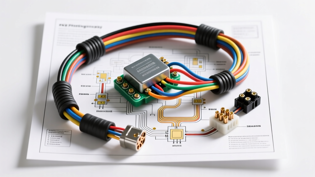
The Simple Motorcycle Starter Relay Wiring Diagram
For custom motorcycle applications, the industry standard is a heavy-duty 4-pin SPST-NO (Single Pole, Single Throw, Normally Open) relay, often referred to as a Bosch-style mini relay or ISO relay. While standard 40A automotive relays are common, a motorcycle starter upgrade requires a relay rated for at least 80A continuous and 120A peak to handle the inrush current of a cold engine.
4-Pin Relay Terminal Pinout
| Terminal Pin | Function | Connection Point | Wire Color (Custom Standard) |
|---|---|---|---|
| 30 | Common / Main Power In | Direct to Battery Positive (+) | Red (Heavy Gauge) |
| 87 | Normally Open / Power Out | Direct to Starter Motor Positive (+) | Red (Heavy Gauge) |
| 86Coil Trigger Input | From Handlebar Starter Button | Yellow or White | |
| 85 | Coil Ground | Chassis Ground or Battery Negative (-) | Black |
Note: On standard ISO relays, pins 85 and 86 are the electromagnetic coil. While they are generally non-polarized on standard relays, if your specific heavy-duty relay includes an internal suppression diode or resistor, pin 86 must be positive and pin 85 must be ground. Always verify with the manufacturer's schematic.
Component & Wire Gauge Specifications
Choosing the correct American Wire Gauge (AWG) is critical. Undersized wires will overheat, melt insulation, and cause severe voltage drop, starving the starter motor of the cranking amps it needs. According to SAE J1171 marine and outdoor electrical standards (which closely apply to exposed motorcycle wiring), wire bundles must be sized not just for amperage, but for length and voltage drop.
| Circuit Segment | Recommended AWG | Connector Type | Protection / Fusing |
|---|---|---|---|
| Battery to Relay (Pin 30) | 6 AWG (4 AWG for runs > 4 ft) | Adhesive-Lined Ring Terminal | 120A ANL Fuse near battery |
| Relay to Starter (Pin 87) | 6 AWG | Adhesive-Lined Ring Terminal | None (Protected by Main ANL) |
| Ignition to Starter Button | 14 AWG | Snap-on Spade / Bullet | 10A ATC Inline Fuse |
| Button to Relay Coil (Pin 86) | 16 AWG | Fully Insulated Female Spade | None |
| Relay Coil Ground (Pin 85) | 16 AWG | Adhesive-Lined Ring Terminal | None |
Step-by-Step Relay Installation & Routing
- Disconnect the Battery: Always remove the negative (-) battery cable first to prevent accidental short circuits while working near the starter and battery positive terminals.
- Mount the Main Fuse: Install a 120A ANL fuse holder within 6 inches of the battery's positive terminal. This protects the main 6 AWG power cable in the event of a dead short against the frame.
- Run the High-Current Cables: Route the 6 AWG red wire from the battery/fuse to Pin 30 on the relay. Route the second 6 AWG red wire from Pin 87 to the starter motor's positive stud. Keep these cables away from the exhaust headers and moving suspension components.
- Wire the Trigger Circuit: Run a 14 AWG wire from a switched 12V ignition source to your handlebar starter button. From the output side of the starter button, run a 16 AWG wire down to Pin 86 on the relay.
- Establish a Clean Ground: Connect a 16 AWG black wire from Pin 85 to a clean, bare-metal point on the motorcycle's frame or engine block. Sand away any paint or powder coating at the grounding point to ensure zero resistance.
- Crimp and Seal: Do not use solder on high-vibration motorcycle wiring; solder wicks into the wire strands and creates a brittle stress point that will snap under engine vibration. Use a high-quality ratcheting crimper and seal all connections with marine-grade, adhesive-lined heat shrink tubing to prevent moisture intrusion and corrosion.
Voltage Drop Testing in Extended Choppers
When building extended choppers or bikes with long wire runs (such as a battery relocated to the rear fender or under the seat), voltage drop becomes a major enemy. A starter motor requires a minimum of 10.5 volts at the terminal to crank a high-compression engine effectively. If you run 20 feet of total cable (positive and negative combined) using 8 AWG wire, the resistance will cause a significant voltage drop.
As documented in various ElectroSport technical articles regarding motorcycle charging and starting systems, upgrading to 4 AWG or even 2 AWG battery cables is mandatory for extended frames. After completing your simple motorcycle starter relay wiring diagram setup, use a digital multimeter to perform a voltage drop test. Place one probe on the battery positive post and the other on the starter motor terminal while cranking. A reading higher than 0.5 volts indicates excessive resistance in your cables, crimps, or relay contacts.
Troubleshooting Common Relay Modification Failures
Even with a flawless wiring diagram, custom builds can present unique electrical gremlins. Use this diagnostic tree if your upgraded starter circuit fails to engage:
- Symptom: Relay clicks, but starter does not turn.
- Cause: High resistance on the high-current side (Pins 30/87) or a weak battery.
- Fix: Check for voltage drop across the relay's main terminals while cranking. If the drop exceeds 0.2V, the relay contacts are undersized or pitted. Replace with a higher-amperage rated relay or clean the battery/ground connections.
- Symptom: No click from the relay when the button is pressed.
- Cause: Open circuit in the low-current trigger side (Pins 85/86) or a faulty handlebar switch.
- Fix: Use a test light or multimeter to verify 12V is reaching Pin 86 when the button is depressed. Check the ground at Pin 85. Inspect the handlebar switch for internal corrosion or melted contacts.
- Symptom: Starter continues to crank after releasing the button.
- Cause: The relay's internal contacts have welded together due to extreme arcing from an undersized relay or a failing starter motor drawing excessive amperage.
- Fix: Immediately disconnect the battery. Replace the relay with a heavy-duty 120A+ model and have the starter motor bench-tested for internal short circuits or worn bushings causing high amp draw.
Final Expert Advice
Always apply a thin layer of dielectric grease to the relay's spade terminals before pushing them into the socket. This prevents galvanic corrosion, which is especially prevalent on custom motorcycles exposed to the elements. By properly executing this simple motorcycle starter relay wiring diagram, you ensure reliable, high-torque cranking for years to come, while completely protecting your custom handlebar controls from electrical destruction. For more advanced custom wiring schematics, consult the Bosch Automotive Technology relay databases to verify specific coil resistance and diode orientations for your exact relay model.