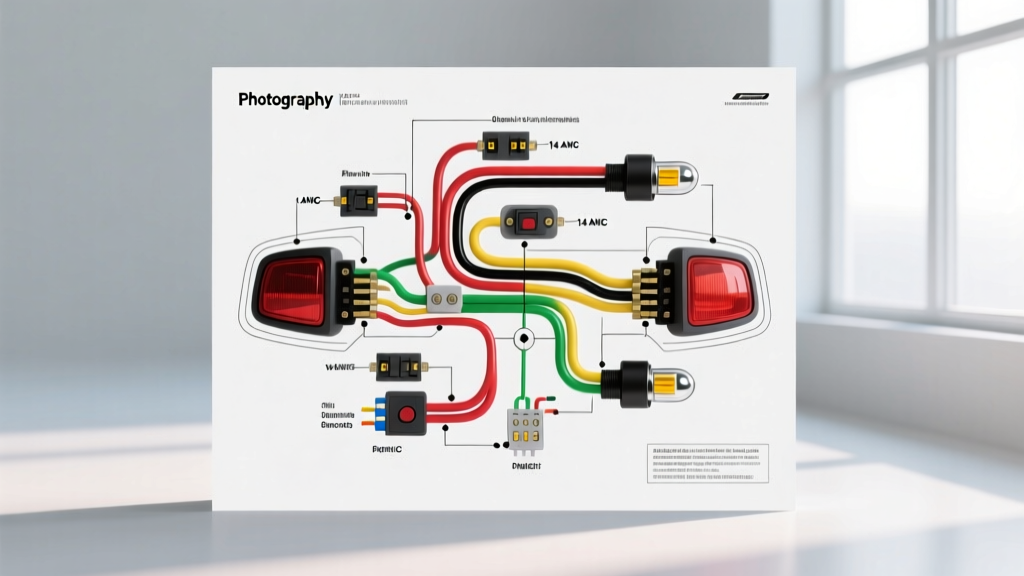
Decoding the Wiring Diagram for Brake Lights: A Beginner's Foundation
Whether you are restoring a classic muscle car or diagnosing a daily driver, understanding a wiring diagram for brake lights is a fundamental automotive electrical skill. Unlike complex data-bus networks, the traditional brake light circuit is a straightforward DC power loop. However, modern vehicles integrate this loop into the Body Control Module (BCM) and anti-lock braking systems (ABS). This guide breaks down the schematics, wire gauges, and routing paths you need to trace, repair, and verify your stop lamp circuits safely and accurately.
Standard Wire Gauges and OEM Color Codes
Automotive manufacturers follow strict SAE International J586 guidelines for stop lamp illumination and circuit protection. Selecting the correct American Wire Gauge (AWG) is critical to prevent voltage drop and wire overheating, especially when upgrading to high-draw incandescent bulbs or adding trailer towing harnesses.
| Circuit Segment | Recommended AWG | Common GM Colors | Common Ford Colors | Fuse Rating |
|---|---|---|---|---|
| Main Switch Feed | 14 AWG | Light Blue / White | Light Green / Red Hash | 15A - 20A |
| Switch to Turn Signal | 14 AWG | White | Light Green | N/A (Downstream) |
| Left Rear Output | 16 AWG | Yellow | Light Green / Orange | N/A (Downstream) |
| Right Rear Output | 16 AWG | Dark Green | Orange / Light Blue | N/A (Downstream) |
| Trailer Adapter Feed | 12 AWG (Min) | Red (Aux) | Red (Aux) | 30A (w/ Relay) |
The Multi-Function Switch: Where Brake and Turn Signals Meet
One of the most confusing aspects for beginners reading a brake light schematic is discovering that the brake light wire does not go directly to the rear bulbs on most pre-2005 domestic vehicles. Instead, the circuit routes through the steering column's multi-function switch (turn signal lever).
How the Gating Logic Works
- Normal State: When the turn signal lever is centered, the multi-function switch acts as a simple pass-through. The 12V+ from the brake switch flows directly to both the left and right rear 1157 dual-filament bulbs (or 3157 wedge bases).
- Left Turn Active: If you signal left while braking, the switch physically disconnects the left rear brake feed from the brake switch and connects it to the hazard/turn flasher module. The left bulb flashes, while the right bulb remains solidly illuminated by the brake switch.
When diagnosing a 'one brake light out' issue where the bulb and socket are confirmed good, the fault almost always lies in the copper contact wafers inside the multi-function switch, which suffer from carbon tracking and grease degradation over time.
Modern Architecture: BCM Logic and Low-Side Drivers
If your wiring diagram for brake lights shows a module with dozens of pins rather than a simple mechanical switch, you are looking at a modern Body Control Module (BCM) architecture. In vehicles from 2010 onward, the brake pedal switch is rarely a high-amperage 12V load switch. Instead, it is a low-current logic sensor.
Tracing a BCM Brake Circuit
- The Sensor: The pedal assembly houses a Hall-effect or dual-circuit micro-switch. It sends a 5-volt reference signal back to the BCM when the pedal is depressed.
- The BCM Logic: The BCM receives this logic ground/signal. It cross-references it with wheel speed sensors (for cruise control cancellation) and transmission range sensors.
- The Output Driver: The BCM triggers an internal low-side MOSFET to supply 12V+ to the rear LED stop lamps. These outputs are often pulse-width modulated (PWM) or monitored for current draw to detect burnt-out bulbs without a physical filament.
Expert Warning: Never probe a BCM output wire with a standard incandescent test light. The high inrush current of the test light bulb can instantly destroy the BCM's internal solid-state driver. Always use a high-impedance digital multimeter (DMM) or an LED logic probe.
Systematic Troubleshooting: From Fuse to Ground
Follow this structured diagnostic path when your wiring diagram indicates a complete brake light failure. Reference Haynes Wiring Tutorials for vehicle-specific ground location maps.
Step 1: Verify the Power Source
Locate the 'STOP LP' or 'BTSI' (Brake Transmission Shift Interlock) fuse in the under-hood or instrument panel fuse block. Use a DMM to check for 12V on both test points on the top of the fuse. If power is missing on both sides, trace back to the main battery junction block. If power is present on one side but not the other, replace the fuse and check for a dead short to ground in the 14 AWG feed wire.
Step 2: Test the Switch Inputs and Outputs
Unplug the brake switch connector (typically a 2-pin or 4-pin Metri-Pack 150 or 280 series). With the pedal depressed, check for 12V at the input pin. If present, use a jumper wire to bridge the input and output pins. If the rear lights illuminate, the wiring is intact, and the mechanical switch plunger is out of adjustment or failed.
Step 3: Inspect Ground Points (G-Series)
A common failure mode is a corroded ground splice pack or ring terminal. Rear light grounds (often labeled G300 or G400 in GM schematics) are typically located in the trunk pan or behind the rear quarter panel trim. A bad ground will cause 'backfeeding,' where pressing the brake pedal causes the tail lights to dimly illuminate alongside the brake filaments due to current seeking a path through the parking light circuit.
Connector Types and Terminal Extraction
Repairing a damaged wire requires more than just twisting and taping. Professional diagrams specify the connector cavity and terminal type. For brake light circuits, you will frequently encounter:
- Weather-Pack (Sealed): Used near the frame rail and trailer hitches. Features a silicone ribbed seal. Terminals must be crimped with a specific open-barrel tool.
- Metri-Pack 280 (Unsealed/Pull-to-seat): Common at the brake pedal switch under the dash. The locking tang is on the terminal itself, requiring a specialized pick tool to depress the tang for extraction.
- Bulb Sockets: Standard 1157 (bayonet) or 3057/3157 (wedge) sockets. Always apply dielectric grease to the socket contacts to prevent galvanic corrosion between the aluminum socket housing and brass bulb base, a best practice highlighted in Littelfuse automotive protection guides.
Final Thoughts on Schematic Literacy
Mastering the wiring diagram for brake lights bridges the gap between a parts-swapper and a true diagnostic technician. By understanding the transition from simple mechanical pass-throughs to complex BCM logic gates, and by respecting AWG limits and connector seals, you ensure your vehicle's stop lamps operate reliably. Always disconnect the negative battery terminal before performing hard-wire splices, and verify your repairs with a voltage-drop test across the entire circuit under load.