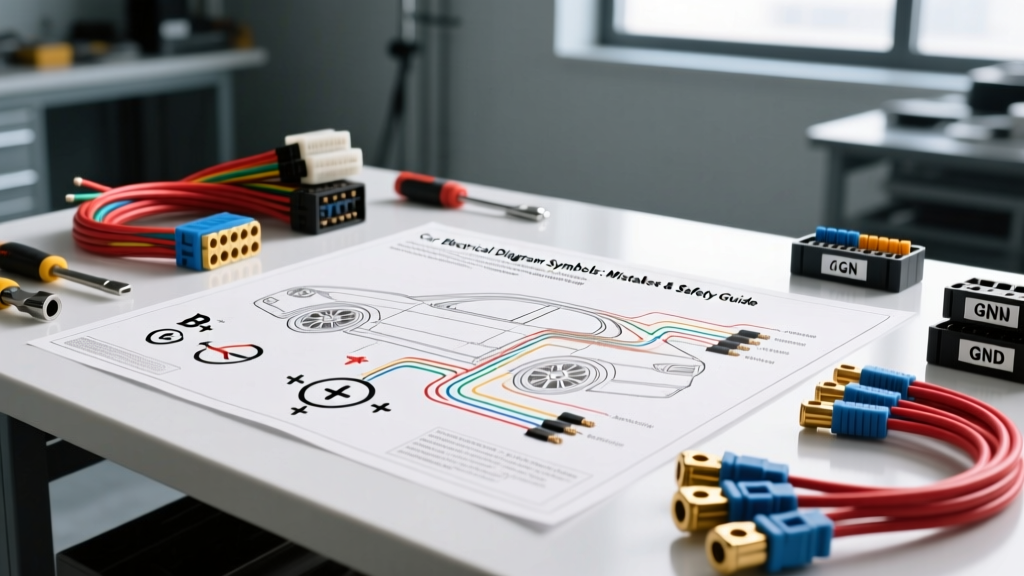
The Hidden Dangers of Misinterpreting Schematics
Understanding car electrical diagram symbols is the fundamental difference between a successful, efficient diagnosis and a catastrophic $1,500 PCM replacement. Modern vehicles rely heavily on multiplexed networks (CAN, LIN, FlexRay), sensitive 5-volt reference circuits, and complex pulse-width modulation (PWM) signals. A single misinterpreted symbol on a wiring schematic can lead a technician to probe the wrong circuit, inadvertently shorting a logic board or corrupting a high-speed data bus. This guide breaks down critical car electrical diagram symbols from a safety-first perspective, highlighting common mistakes that lead to blown fuses, damaged modules, and inaccurate diagnostic trouble codes (DTCs).
Essential Car Electrical Diagram Symbols Decoded
Before touching a digital multimeter (DMM) or a breakout box, you must accurately translate the schematic. OEM service manuals (from GM, Ford, Toyota, etc.) generally adhere to SAE J1292 standards for electrical symbology, though minor regional variations exist. Below is a reference table of critical symbols and the severe mistakes associated with them.
| Symbol / Representation | Meaning & Application | Common Fatal Mistake |
|---|---|---|
| Solid Dot (Node) | Splice or internal harness junction. Wires are physically and electrically connected. | Assuming it is merely two wires crossing over each other without connecting, leading to incorrect continuity testing. |
| Open Circle / Box | Connector interface (e.g., Delphi Metri-Pack 280). Indicates where a harness meets a component or another harness. | Piercing the wire insulation near the connector instead of properly backprobing the terminal, causing moisture ingress and future corrosion. |
| Zig-Zag Line | Resistor. Used in thermistors (IAT, ECT), pull-up/pull-down resistors, and blower motor resistors. | Confusing a standard resistor symbol with a heating element symbol (often a zig-zag inside a box), leading to incorrect amperage draw expectations. |
| Box with Diagonal Line | Relay Coil / Switch. Represents the electromagnetic coil and the internal switch contacts. | Misidentifying the low-current control side (85/86) with the high-current load side (30/87), resulting in back-feeding 12V into a PCM driver transistor. |
| Arrow Pointing Down | Chassis / Engine Ground (e.g., G100, G200). Physically bolted to the frame or engine block. | Using a heavy chassis ground to measure a sensitive 5V logic signal, introducing voltage drop and throwing false sensor codes. |
| Arrow into a Box | Logic / Internal Ground. A dedicated sensor return path routed back to the PCM internal ground plane. | Testing continuity to the vehicle battery negative terminal instead of the specific PCM pin, missing an open circuit inside the harness. |
Fatal Wiring Mistakes & Safety Warnings
Translating car electrical diagram symbols correctly is only half the battle. Applying the wrong diagnostic technique to the circuit represented by those symbols is where the real damage occurs. Below are the most common and destructive mistakes made in the bay.
Mistake 1: Confusing Chassis Grounds with Logic Sensor Returns
On a schematic, a ground symbol pointing to a line (Chassis Ground) is vastly different from a ground symbol pointing into a module (Logic Ground). Consider the Mass Air Flow (MAF) sensor on a GM 5.3L Vortec engine. The MAF requires a dedicated 5V reference (typically 18 AWG Pink/Black) and a dedicated logic ground (18 AWG Black/White) that routes directly back to the PCM.
If a technician uses a standard chassis ground point (like the alternator bracket) to measure the MAF signal voltage, they are ignoring the voltage drop across the engine-to-chassis ground straps. A mere 0.2V difference between the PCM's internal ground and the chassis ground can cause the PCM to read the MAF signal as skewed, resulting in a phantom P0101 (Mass or Volume Air Flow 'A' Circuit Range/Performance) code. Always measure sensor signals using the specific logic return pin identified in the schematic pinout table.
Mistake 2: Piercing VREF and CAN Bus Wires with Test Lights
One of the most expensive mistakes in modern automotive diagnostics is using a standard incandescent test light or a low-impedance analog multimeter on circuits identified by sensitive data symbols. A standard test light draws between 2 to 3 amps of current.
If you probe a 5-Volt Reference (VREF) circuit—usually 20 AWG or 22 AWG wire—with a test light, the sudden current draw will instantly blow the internal voltage regulator inside the PCM, destroying the module. Similarly, probing Controller Area Network (CAN) lines (CAN-H typically 2.5V-3.5V, CAN-L typically 1.5V-2.5V) with a test light will collapse the network differential voltage. This corrupts the data bus, throws U-codes (e.g., U0100 Lost Communication with ECM/PCM), and can permanently damage the CAN transceiver chip. Always use a high-impedance (10-megohm) Digital Multimeter (DMM) or a dedicated automotive logic probe when interacting with these symbols.
Mistake 3: Ignoring SRS Airbag Safety Protocols
Schematics denote Supplemental Restraint System (SRS) circuits with specific shading or warning flags. These circuits utilize yellow connectors (typically Delphi or Molex sealed series) and contain pyrotechnic squibs.
Safety Warning: Never use a test light, apply external 12V power, or measure resistance with an active DMM on an SRS circuit. The micro-amp output of a multimeter or the heat from a test light can inadvertently deploy an airbag or seatbelt pretensioner, causing severe injury or death. Always disconnect the negative battery terminal and wait a minimum of 15 minutes for the SRS module's backup capacitor to discharge before working near these circuits, as mandated by NHTSA safety guidelines and OEM repair procedures.
Wire Gauge, AWG, and Connector Specifications
A proper understanding of car electrical diagram symbols must be paired with knowledge of physical wire properties. Schematics often denote wire color and gauge (AWG) next to the wire line. Ignoring these specifications leads to improper repairs and voltage drop issues.
- 18 to 22 AWG: Used for sensor signals, CAN bus lines, and low-current PCM drivers. These wires are highly susceptible to voltage drop and physical breakage. Repairs must be soldered and sealed with heat-shrink tubing; crimp connectors are unacceptable for data lines.
- 12 to 14 AWG: Standard for high-current accessories, fuel pump feeds, and injector power circuits. Capable of handling 15A to 20A continuous loads.
- 4 to 8 AWG: Reserved for primary power feeds, such as the alternator B+ terminal, starter solenoid, and main battery-to-fusible-link harnesses.
When a schematic indicates a connector, you must identify the terminal type. The Delphi Metri-Pack 280 series is standard for most under-hood sensors, requiring specific weather-pack seals. The smaller Metri-Pack 150 series is common in PCM connectors. Attempting to force a 280 terminal probe into a 150 connector cavity will spread the terminal tangs, ruining the connector's tension and causing an intermittent open circuit.
Safe Backprobing and Diagnostic Protocols
When a schematic directs you to test at a connector (Open Circle symbol), never pierce the wire insulation. Piercing exposes the copper strands to moisture, leading to capillary corrosion that will wick into the PCM over time. Instead, use the following protocol:
- Identify the Connector: Match the cavity number on the schematic to the physical connector face.
- Use Proper Probes: Utilize T-pin backprobes or OEM-specific breakout boxes that match the terminal width (e.g., 0.64mm, 1.5mm, or 2.8mm blades).
- Insert from the Rear: Gently slide the probe past the weather seal until it makes contact with the terminal mating surface.
- Verify Impedance: Ensure your DMM is set to the correct range (Auto-ranging is preferred) before connecting the ground lead to a verified clean chassis ground or logic return.
Authoritative References
For comprehensive symbol libraries and standardized diagnostic procedures, technicians should consult the following authoritative resources: