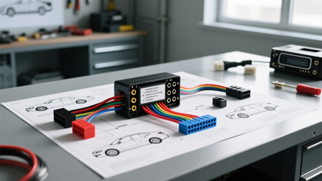
Mastering Car Stereo Wiring Diagrams: A Step-by-Step Troubleshooting Flow
When an aftermarket head unit fails to power on, loses memory, or produces distorted audio, the root cause almost always traces back to a misinterpreted schematic or a poor connection. Reading car stereo wiring diagrams requires more than matching colors; it demands an understanding of ISO 10487 standards, OEM data-bus architectures, and proper multimeter diagnostic flows. This guide provides a systematic, step-by-step troubleshooting sequence for diagnosing head unit wiring faults, from constant power verification to speaker phase validation.
Phase 1: Verifying the Power and Memory Circuits
The most common installation error involves swapping the constant 12V (memory) and switched 12V (accessory) wires. In standard aftermarket car stereo wiring diagrams, yellow represents constant battery power (B+), while red represents ignition-switched power (ACC). However, European vehicles utilizing the ISO 10487 standard often reverse these pins at the factory harness.
Diagnostic Steps for Power Circuits
- Set your Digital Multimeter (DMM) to DC Voltage. Connect the black probe to a known good chassis ground.
- Test the Constant Wire (Yellow / ISO Block A, Pin 4): Probe the wire with the key OFF. You should read 12.2V to 12.6V. If you read 0V, check the inline fuse (typically 10A or 15A) and the vehicle's interior fuse panel.
- Test the Switched Wire (Red / ISO Block A, Pin 7): Turn the ignition to the ACC or ON position. Voltage should jump to 11.5V - 12.5V. If the stereo loses its radio presets every time you turn off the car, these two circuits are reversed at the harness adapter.
Expert Insight: Modern high-power head units (4x50W MOSFET) can draw up to 15 amps at peak volume. Ensure the constant power wire is at least 16 AWG, and preferably 14 AWG, routed directly to the battery with an inline MAXI fuse if the factory harness uses thin 18 AWG wiring.
Phase 2: Ground Circuit Validation and Voltage Drop
A poor ground causes alternator whine, screen flickering, and thermal shutdown. Standard diagrams indicate a black wire for ground (ISO Block A, Pin 8). While it is tempting to connect this to the factory harness ground, factory ground wires are often daisy-chained with low-current interior lighting circuits, leading to voltage starvation under heavy bass transients.
The Voltage Drop Test
Never rely solely on a continuity beep to verify a ground. Perform a dynamic voltage drop test:
- Turn the stereo on and raise the volume to 75% to induce a current draw.
- Set your DMM to DC Voltage.
- Place the red probe on the head unit's metal chassis or the black ground wire's terminal.
- Place the black probe on a clean, unpainted metal point on the vehicle chassis.
- A reading above 0.1V (100mV) indicates excessive resistance. Sand the chassis mounting point and use a star washer to bite through the paint, or run a dedicated 12 AWG ground wire to a primary chassis bolt.
Phase 3: Accessory Triggers, Illumination, and Amp Turn-On
Accessory triggers control external amplifiers, motorized antennas, and display dimming. Miswiring these leads to blown fuses or parasitic battery drains.
- Amp Turn-On (Blue/White): Provides +12V only when the unit is powered on. Failure Mode: Connecting this to the constant 12V source will leave your amplifiers on permanently, draining the battery overnight. Furthermore, the internal turn-on lead is usually 18 AWG and limited to 300mA. If triggering multiple amplifiers, use a 30A automotive relay to handle the remote turn-on current.
- Illumination (Orange): Sends a +12V signal when headlights are turned on, dimming the display. Failure Mode: Many modern vehicles (e.g., Dodge/Chrysler, Ford) use a PWM (Pulse Width Modulation) dimmer circuit rather than a simple +12V trigger. Connecting a standard aftermarket orange wire directly to a PWM CAN-bus dimmer circuit can backfeed voltage and fry the head unit's microprocessor. Always use a CAN-bus interface module for these vehicles.
Phase 4: Speaker Output and Phase Troubleshooting
Standard car stereo wiring diagrams follow the Electronic Industries Alliance (EIA) RS-770 color code standard for speaker outputs (ISO Block B). Correct phase alignment is critical for bass response and sound staging.
| Speaker Location | Positive Wire (+) | Negative Wire (-) | ISO Block B Pinout |
|---|---|---|---|
| Left Front | White | White/Black Stripe | Pin 1 (+) / Pin 5 (-) |
| Right Front | Gray | Gray/Black Stripe | Pin 2 (+) / Pin 6 (-) |
| Left Rear | Green | Green/Black Stripe | Pin 3 (+) / Pin 7 (-) |
| Right Rear | Purple | Purple/Black Stripe | Pin 4 (+) / Pin 8 (-) |
Testing for Out-of-Phase Speakers
If the bass sounds hollow or the soundstage feels disconnected from the center dash, your speakers are likely out of phase. Use a 9V battery to perform a quick physical polarity test on the factory harness before connecting the head unit. Briefly touch the positive and negative wires to the battery terminals; if the speaker cone pushes outward, the wire touching the positive battery terminal is the true positive (+). For installed systems, use a digital phase tester or play a mono bass track and pan the fader left-to-right to identify cancellation nodes.
Phase 5: Advanced OEM Data Bus Integration (CAN / GMLAN)
In vehicles manufactured after 2005, traditional car stereo wiring diagrams are often incomplete because power and accessory triggers are managed via digital data networks rather than discrete copper wires.
- Chrysler / VW / Audi (CAN-bus): The accessory trigger is broadcast over the CAN-H and CAN-L twisted pair. You cannot tap a physical 12V ACC wire. A data interface (e.g., PAC RP4-CH11 or Axxess XSVI) is required to translate the CAN-bus digital signal into a standard 12V analog turn-on wire.
- General Motors (Class 2 GMLAN): GM vehicles use a single-wire data bus. The factory radio receives the ignition status and chime signals via this network. Bypassing the data module and hardwiring to the ignition cylinder will disable the vehicle's anti-theft passlock system and door chimes.
When diagnosing a no-power condition in a data-bus vehicle, verify that the interface module is receiving both 12V constant and a valid CAN network signal. Use an oscilloscope to verify the CAN-H (typically 2.5V to 3.5V) and CAN-L (1.5V to 2.5V) differential voltages.
Authoritative References and Standards
To ensure safe and compliant installations, always cross-reference your vehicle-specific schematics with established industry standards. The wiring protocols outlined in this troubleshooting flow are based on the following authoritative resources:
- ISO 10487 Standard: Defines the physical dimensions and pin assignments for car radio connectors (Block A for power, Block B for speakers). Refer to the ISO 10487 documentation for exact pinout matrices.
- MECP (Mobile Electronics Certification Program): The industry benchmark for installation practices, wire gauge sizing, and EIA color code compliance. Visit MECP.com for certification manuals and wiring best practices.
- SAE J1113 (Electromagnetic Compatibility): Crucial for understanding how to route speaker and RCA cables away from power wires to prevent alternator whine and EMI interference. See SAE International's EMC guidelines for automotive electrical routing standards.
By following this step-by-step diagnostic flow, you can systematically eliminate wiring faults, protect sensitive microprocessors from backfeed voltage, and ensure your audio system performs exactly as engineered.