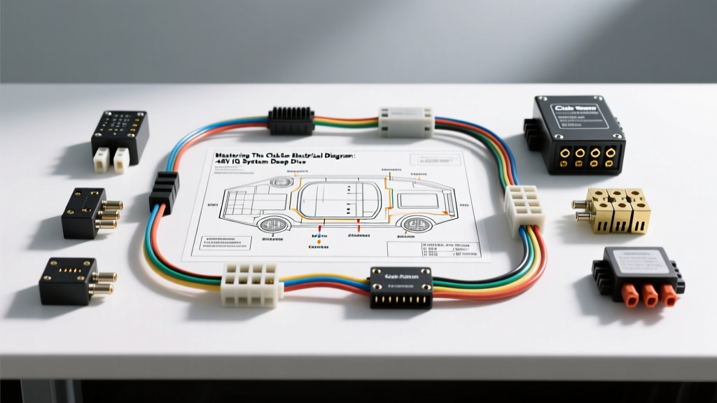
Introduction to the 48V IQ Architecture
When diagnosing a modern 48V electric fleet vehicle, referencing the correct club car electrical diagram is the difference between a precise repair and a catastrophic controller failure. The Club Car Precedent IQ (and subsequent Excel) systems represent a massive paradigm shift from the older 36V resistor-coil and V-Glide setups. Instead of mechanical resistance, the IQ system utilizes a solid-state 48V DC motor controller, an inductive Motor Controller Output Regulator (MCOR) for throttle input, and an On-Board Computer (OBC) that manages charge logic and system lockouts.
This advanced technical deep dive bypasses basic troubleshooting and dissects the high-current traction loops, low-voltage logic interlocks, and specific wire gauge routing required to maintain peak efficiency and safety in these Neighborhood Electric Vehicles (NEVs). For foundational EV electrical safety and testing protocols, technicians should always adhere to SAE J1715 standards for HEV/EV terminology and safety.
High-Current Traction Circuit: AWG & Routing Specifications
The primary traction circuit is responsible for delivering sustained high amperage from the battery bank to the motor via the main solenoid and controller. Voltage drop in this circuit is the leading cause of thermal runaway and controller MOSFET failure.
- Battery Interconnects: 4 AWG pure copper, tinned marine-grade cable. Torque terminal nuts to 90-110 in-lbs. Any corrosion here introduces resistance that the OBC will interpret as a failing battery bank.
- Main Traction Cables (Battery to Solenoid/Controller): 2 AWG ultra-flex welding cable. The IQ system can pull upwards of 350A during initial startup or steep incline regenerative braking. Using standard 4 AWG automotive primary wire here will result in severe voltage sag and insulation melting.
- Motor Terminals: The connection from the controller to the separately excited (SepEx) DC motor utilizes four 2 AWG cables (Armature A1/A2 and Field F1/F2). Terminal torque specification is strictly 120 in-lbs. Under-torquing causes arcing; over-torquing strips the copper studs on the motor housing.
The MCOR (Motor Controller Output Regulator) Pinout & Logic
Early golf carts used potentiometers that wore out mechanically. The Precedent IQ utilizes an MCOR, which translates physical pedal movement into a variable voltage signal sent to the controller's logic board. Later iterations use non-contact inductive or Hall-effect sensors to eliminate physical wiper degradation. The MCOR features a redundant dual-signal track to allow the controller to detect internal sensor faults and trigger a rollback-prevention lockout.
MCOR 4-Pin Diagnostic Table
When back-probing the 4-pin MCOR connector (harness side to controller), use a high-impedance digital multimeter. According to Fluke's EV component testing guidelines, always use the MIN/MAX function to catch microsecond voltage dropouts caused by internal sensor track degradation.
| Pin | Wire Color | Function | Resting Voltage (Pedal Up) | Full Throttle (Pedal Down) |
|---|---|---|---|---|
| 1 | Red | 5V VCC (Logic Power) | 5.0V DC | 5.0V DC |
| 2 | Black | Sensor Ground | 0.0V DC | 0.0V DC |
| 3 | White | Signal 1 (Primary) | 0.8V DC | 4.2V DC |
| 4 | Green | Signal 2 (Redundant) | 4.2V DC | 0.8V DC |
Diagnostic Note: If Signal 1 and Signal 2 do not sweep inversely and symmetrically, the controller will throw an HPD (High Pedal Disable) fault code and refuse to engage the solenoid. Do not attempt to adjust the physical pedal box to fix an asymmetric voltage sweep; the MCOR unit must be replaced.
Solenoid Activation and Pre-Charge Circuitry
The main solenoid (typically an Albright SW200 or OEM equivalent 1014336) acts as the high-amperage bridge between the battery pack and the controller's main capacitors. However, closing a 48V circuit directly into empty capacitors causes an inrush current spike that can easily exceed 1000A, welding the solenoid contacts shut or blowing the controller's main fuse.
The Pre-Charge Circuit
To prevent this, the club car electrical diagram incorporates a pre-charge resistor (typically 250 Ohm, 2W to 5W) wired in parallel across the large solenoid terminals. When the key is turned on and the Tow/Run switch is engaged, the OBC and controller logic energize a small internal relay or utilize the microswitches to send a trickle current through this resistor, slowly charging the controller's capacitors. Only after the voltage differential drops below a safe threshold does the main solenoid coil receive full pack voltage to close the heavy contacts.
- Solenoid Coil Resistance: 14.5 to 16.0 Ohms. A reading below 12 Ohms indicates shorted windings; above 20 Ohms indicates an open coil.
- Suppression Diode: A reverse-biased flyback diode is installed across the small solenoid terminals. This absorbs the back-EMF spike when the solenoid is deactivated, protecting the controller's delicate logic board MOSFETs. If this diode fails open, the controller will eventually suffer logic board burnout.
Tow/Run and F/R Switch Interlocks
The logic circuit operates on 16 AWG primary wire, utilizing color-coded tracing to denote specific interlocks. The Forward/Reverse (F/R) switch and the Tow/Run switch are in series with the solenoid activation path.
- Tow/Run Switch: Located in the passenger side panel. In 'RUN', it completes the logic ground path. In 'TOW', it physically isolates the controller logic from the battery pack. Warning: Towing a Precedent IQ in the 'RUN' position turns the SepEx motor into a generator. The resulting back-EMF will bypass the discharged battery bank and directly strike the controller, resulting in catastrophic, unrepairable internal shorting.
- F/R Microswitches: The mechanical F/R rocker actuates two distinct microswitches. The Forward switch routes 16 AWG Yellow/Black wires to the controller's FWD pin. The Reverse switch routes Yellow/White wires. If the cart moves in reverse but the backup beeper does not sound, check the 12V step-down converter tap on the F/R reverse logic line.
On-Board Computer (OBC) Lockout Logic
The 6-pin OBC is the brain of the charging system, but it also holds veto power over the traction circuit. The OBC monitors the charge receptacle. If it detects an AC voltage presence or a fault in the battery string (e.g., a single 8V battery dropping below 10.5V under load), the OBC will open its internal lockout relay. This relay sits in series with the solenoid activation wire (usually 16 AWG Blue/White). When troubleshooting a 'no-click' solenoid issue where the MCOR and F/R switches test perfectly, bypassing the OBC lockout relay temporarily will confirm if the OBC is falsely inhibiting the vehicle.
Advanced Troubleshooting Decision Tree
When facing a dead 48V Precedent IQ, follow this structured diagnostic path rather than blindly replacing parts. Comprehensive wiring schematics and community-verified diagrams can be cross-referenced via established technical archives like Buggies Gone Wild's Club Car repository.
Symptom: Solenoid Clicks, But Motor Does Not Engage
- Check Main Cable Voltage Drop: Measure voltage across the large solenoid terminals while the pedal is pressed. If it reads >0.5V DC, the solenoid contacts are pitted and carbonized. Replace the solenoid.
- Verify Controller Output: Check the F1/F2 field terminals at the motor. The controller should output a varying PWM voltage to the field to control speed. If field voltage is present but the motor doesn't spin, the armature brushes are likely worn below the 1/2 inch service limit.
- Inspect Motor Speed Sensor: The SepEx motor relies on a hall-effect speed sensor inside the motor housing to tell the controller the rotor's position. If the sensor fails, the controller will cut power to prevent runaway acceleration. Test sensor output for a 5V square wave pulse while the cart is jacked up and wheels are spun.
Symptom: No Solenoid Click, Tow/Run is in RUN
- Verify Logic Power: Check the 16 AWG Red/White wire at the key switch for full pack voltage (approx 50.4V fully charged).
- Test F/R Interlock: Bypass the F/R microswitches with a jumper wire. If the cart engages, the microswitch alignment plate is bent, preventing the plunger from fully depressing.
- OBC Lockout Bypass: Disconnect the 6-pin OBC harness. Jump the Blue/White wire (solenoid feed) directly to the 16 AWG Red wire (key switch power). If the solenoid clicks, the OBC has detected a battery fault or charge plug fault and is inhibiting the drive circuit.
Conclusion
Maintaining a 48V Club Car Precedent IQ requires a fundamental understanding of both high-amperage DC traction principles and low-voltage logic interlocks. By strictly adhering to the AWG specifications, verifying the inverse symmetry of the MCOR signals, and respecting the OBC's protective lockouts, technicians can ensure maximum uptime and prevent costly collateral damage to the vehicle's solid-state architecture.