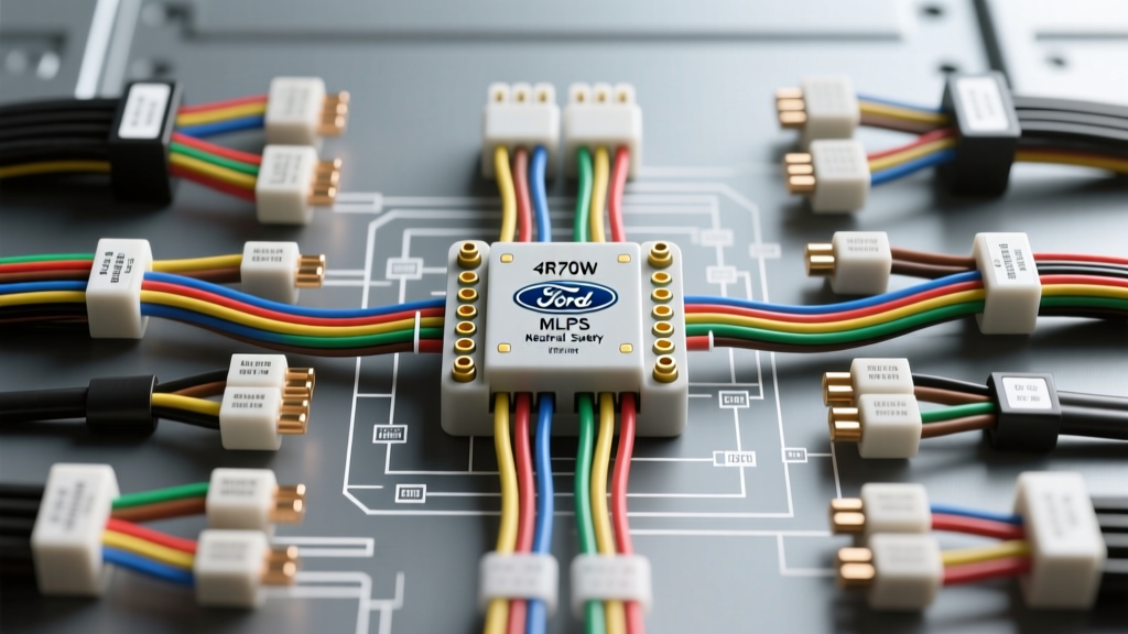
Understanding the Neutral Safety Switch and MLPS Architecture
When technicians and DIYers search for a wiring diagram for neutral safety switch circuits, they are often looking at outdated mechanical schematics. In modern and late-model vehicles, the traditional mechanical Neutral Safety Switch (NSS) has evolved into the Transmission Range Sensor (TRS) or Manual Lever Position Sensor (MLPS). This component performs two critical, yet electrically distinct, functions: it acts as a high-current safety interlock to prevent the engine from cranking in gear, and it provides a low-current digital logic signal to the Powertrain Control Module (PCM) for shift scheduling and line pressure control.
Mixing up these two distinct electrical domains within the same multi-pin connector is the leading cause of catastrophic wiring failures, PCM damage, and severe safety hazards. This guide focuses on the widely used Ford 4R70W transmission MLPS (found in F-150s, Mustangs, and Crown Victorias), detailing the exact pinouts, common wiring mistakes, and critical safety warnings you must follow before probing or splicing these circuits.
Ford 4R70W MLPS Pinout and Wiring Specifications
The Ford 4R70W MLPS utilizes an 8-pin rectangular connector. It is vital to understand that this single connector houses both heavy-gauge starter relay feeds and delicate 18 AWG PCM signal wires. Below is the definitive specification chart for this connector.
| Pin | Circuit Name | OEM Wire Color | AWG | Function / Destination |
|---|---|---|---|---|
| 1 | P/N Start Enable | Red/Light Blue (RD/LB) | 12 AWG | Ignition Switch to Starter Relay Coil |
| 2 | Backup Lamps | Black/Pink (BK/PK) | 14 AWG | MLPS to Backup Lamp Relay / Lamps |
| 3 | OD Cancel Switch | Light Green/Red (LG/RD) | 18 AWG | Steering Column O/D Button to PCM |
| 4 | TR Signal 1 | White/Yellow (WT/YL) | 18 AWG | PCM Digital Input (Pin 30) |
| 5 | TR Signal 2 | Gray/Red (GY/RD) | 18 AWG | PCM Digital Input (Pin 15) |
| 6 | TR Signal 3 | Yellow/White (YL/WT) | 18 AWG | PCM Digital Input (Pin 60) |
| 7 | TR Signal 4 | Violet/White (VT/WT) | 18 AWG | PCM Digital Input (Pin 25) |
| 8 | Signal Return | Black/White (BK/WT) | 18 AWG | PCM Ground / Chassis Ground |
Top 4 Wiring Mistakes When Repairing the NSS / MLPS
Mistake 1: Cross-Splicing 12 AWG Starter Feeds with 18 AWG PCM Signals
Because Pins 1 and 4-7 reside in the same harness boot, a common and dangerous error is misidentifying a damaged wire and splicing a heavy 12 AWG starter feed into an 18 AWG PCM signal trace. Pin 1 carries the full ignition-crank amperage required to energize the starter relay coil. If a technician accidentally routes this 12V high-current feed into the PCM's 5V reference or digital input pins (Pins 4-7), it will instantly fry the PCM's internal driver board. Always verify wire gauge and use a multimeter to trace the circuit back to the ignition switch or PCM before making any solder or crimp connections.
Mistake 2: Bypassing the MLPS to "Fix" a No-Crank Condition
Some DIYers attempt to bypass the neutral safety function by jumping Pin 1 to a constant 12V source or bridging the connector to force the vehicle to start. While this might engage the starter, it leaves the PCM entirely blind to the transmission's gear position. According to Haynes Wiring Manuals, the PCM relies on the binary combinations of Pins 4 through 7 to determine if the transmission is in Park, Reverse, Neutral, or Drive. If the PCM defaults to an unknown gear state, it will trigger DTC P0708, command maximum line pressure (resulting in bone-shattering shifts), and disable the torque converter clutch (TCC).
Mistake 3: Ignoring the Mechanical Alignment Marks
The MLPS is not just an electrical switch; it is mechanically tied to the transmission's manual valve lever. The sensor housing features two alignment dimples. When the transmission is physically in Neutral, the dimples on the inner and outer rings must align perfectly, allowing you to insert a 1/16" drill bit or alignment pin through the holes. Failing to use this alignment pin before tightening the MLPS mounting bolts (torqued to exactly 80 lb-in or 9 Nm) will cause the electrical contacts to misalign with the mechanical gear detents. The truck may start perfectly in Park, but the PCM will "think" it is in Reverse, causing severe shifting anomalies.
Mistake 4: Using Standard Dielectric Grease on Signal Pins
While dielectric grease is excellent for waterproofing the outer rubber boot of the connector, packing it directly onto the 18 AWG signal pins (Pins 4-7) can cause high-resistance voltage drops. The PCM reads these TR signals as simple 0V or 5V logic states. A thick layer of non-conductive grease can push the delicate terminal contacts apart, resulting in intermittent signal loss and erratic shifting. Clean the terminals with electrical contact cleaner, ensure the rubber weather-pack seal is intact, and apply grease only to the outer perimeter seal.
Symptom-Cause-Fix Decision Tree
Use this structured diagnostic approach before cutting or splicing any wires based on your wiring diagram for neutral safety switch layouts.
- Symptom: No-Crank in Park or Neutral, but dash lights function normally.
- Cause: High resistance or corrosion on Pin 1 (RD/LB) or a failed internal contact in the MLPS.
- Fix: Perform a voltage drop test across Pin 1 while an assistant holds the key in CRANK. A drop greater than 0.5V indicates a bad connection or failed switch. Replace the MLPS or repair the 12 AWG pigtail.
- Symptom: Vehicle starts and runs, but shifts harshly and speedometer drops out.
- Cause: PCM is blind to gear position (Pins 4-7 open circuit) and has entered Fail-Safe mode.
- Fix: Check for continuity between the MLPS connector and the PCM harness. Repair any broken 18 AWG wires and clear the P0708/P0709 codes.
- Symptom: Backup lamps stay on in all gears, or never turn on.
- Cause: Pin 2 (BK/PK) shorted to ground or internal MLPS reverse-contact failure.
- Fix: Disconnect the MLPS. If lamps turn off, the switch is internally shorted. If they stay on, trace the 14 AWG BK/PK wire for a chassis short.
Critical Safety Warnings
The "Lurch" Hazard and Wheel Chocking
Never test the starter enable circuit (Pin 1) without heavily chocking the drive wheels and setting the parking brake. If the MLPS is internally shorted, or if a previous owner incorrectly bypassed the NSS wiring, turning the key to CRANK will engage the starter motor while the transmission is mechanically in gear. This can cause the vehicle to lurch forward or backward with enough torque to cause severe injury or property damage. Always verify the gear selector is in Park and the wheels are blocked before applying power to the starter relay circuit.
Thermal Runaway from Undersized Wiring
As outlined by SAE J1113 standards for automotive electrical systems, wire gauge must be matched to the continuous current load. The starter relay coil on a Ford 4R70W can draw between 3 to 5 amps during cranking. While this seems low, the ignition switch feeds this circuit through a long harness run. Using 16 AWG or 18 AWG wire to replace a damaged Pin 1 (RD/LB) circuit will result in excessive voltage drop, slow cranking speeds, and potential thermal runaway (melting) of the wire insulation under repeated cranking attempts. Always use a minimum of 12 AWG stranded copper for the P/N Start Enable circuit.
Final Diagnostic Verification
After replacing the MLPS or repairing the harness, do not simply start the truck and drive away. Turn the ignition to the ON position (engine off). Have an assistant slowly move the gear selector through every detent (P-R-N-D-2-1) while you monitor a scan tool's PCM Datastream for the TR (Transmission Range) PID. The scan tool must accurately reflect every single gear position. Finally, verify that the engine only cranks in Park and Neutral, and that the backup lamps illuminate exclusively in Reverse. Only after these electrical and mechanical verifications are complete should the vehicle be cleared for road use.