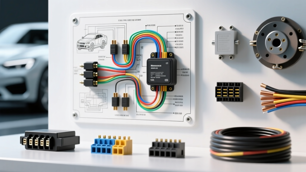
Introduction: The True Cost of Brake Controller Wiring
Installing a trailer brake controller is often mistakenly viewed as a simple plug-and-play upgrade. However, when you are managing up to 30 amps of continuous 12V DC current to activate electromagnetic trailer brakes, precision is non-negotiable. Consulting an accurate wiring diagram for brake controller systems is the first step in preventing catastrophic electrical failures, blown fuses, or worse, a total loss of trailer braking on a steep downgrade. For modern trucks, particularly the Ford F-150 platform (2015-present), the electrical architecture relies heavily on the Body Control Module (BCM). A single miswired pin can backfeed voltage into sensitive solid-state relays, resulting in a $1,500+ BCM replacement and mandatory FORScan programming.
This comprehensive guide approaches the installation from a Cost & Tool Requirements Analysis perspective. We will break down the exact materials, professional-grade tools, and hidden expenses associated with executing a flawless brake controller wiring job, ensuring your rig is safe, legal, and reliable.
Decoding the Wiring Diagram for Brake Controller Circuits
Before purchasing a single foot of wire, you must understand the standard 7-Way RV blade connector, which serves as the primary interface between your truck and the trailer. The SAE J286 standard and RVIA guidelines dictate specific color codes and gauge requirements to prevent voltage drop and overheating. The most critical circuit in your wiring diagram for brake controller setups is the blue output wire, which carries the modulated pulse-width signal from the controller to the trailer's brake magnets.
SAE J286 / RVIA 7-Way Pinout & Wire Specifications
| Pin Position | Function | Standard Wire Color | Minimum AWG (OFC) | Max Continuous Amps |
|---|---|---|---|---|
| 1 o'clock | 12V Auxiliary / Battery Charge | Black | 10 AWG | 30A |
| 3 o'clock | Right Turn / Stop Lights | Green | 12 AWG | 15A |
| 5 o'clock | Ground (Return to Battery) | White | 10 AWG | 40A+ |
| 7 o'clock | Left Turn / Stop Lights | Yellow | 12 AWG | 15A |
| 9 o'clock | Tail / Running Lights | Brown | 12 AWG | 15A |
| 11 o'clock | Output to Trailer Electric Brakes | Blue | 10 AWG | 30A |
| Center | Auxiliary / Reverse Lockout | Red / Purple | 14 AWG | 10A |
Expert Note: Never use Copper-Clad Aluminum (CCA) wire for the blue brake circuit or white ground circuit. CCA has higher electrical resistance and is highly susceptible to galvanic corrosion when exposed to road salt and moisture, leading to rapid voltage drop and weak trailer braking. Always specify Oxygen-Free Copper (OFC).
Tool Requirements: Professional vs. DIY Budget Allocation
The difference between a reliable towing setup and a roadside electrical fire often comes down to the tools used to terminate the connections. Relying on cheap, stamped-metal crimpers and electrical tape is a primary cause of high-resistance joints. Below is an analysis of the tool requirements and their associated costs.
Essential Wiring & Termination Tools
- Wire Strippers (10-18 AWG): Precision stripping is required to avoid nicking the copper strands, which reduces the wire's ampacity. Budget: $15 (Basic) | Pro: $45 (Knoweasy or Titan automatic strippers).
- Ratcheting Crimper for Heat-Shrink Terminals: A ratcheting crimper ensures a uniform, gas-tight crimp that withstands engine bay vibrations. Budget: $20 | Pro: $65 (Iwiss or Glarks).
- Digital Multimeter (DMM): Essential for verifying the 12V input, checking the stoplight switch trigger, and performing voltage drop tests on the blue brake wire. Budget: $25 (Innova 3320) | Pro: $150 (Fluke 115).
- Heat Gun: For properly sealing adhesive-lined heat shrink terminals, which provide environmental protection against moisture and corrosion. Budget: $20 | Pro: $50 (Milwaukee M18 Compact).
- Circuit Tester / Logic Probe: To safely identify the OEM stoplight switch circuit without piercing wire insulation. Cost: $15.
Comprehensive Cost Breakdown: OEM vs. Universal Harness
When planning your installation, you must decide between utilizing the factory tow package pigtail (if equipped) or splicing into a universal 7-way socket. For vehicles like the Ford F-150 with the factory Class IV receiver, an OEM plug-and-play harness (e.g., Ford part #3023-P or Tekonsha 3023-P) drastically reduces labor time and eliminates the risk of voiding the vehicle's electrical warranty.
Material & Component Cost Analysis
| Component | DIY / Universal Route | OEM / Plug-and-Play Route | Cost Difference |
|---|---|---|---|
| Brake Controller (e.g., Tekonsha Prodigy P3) | $145.00 | $145.00 | $0.00 |
| Wiring Harness / Pigtail | $35.00 (Universal 7-way & splices) | $25.00 (OEM Adapter Harness) | -$10.00 (OEM is cheaper & safer) |
| 10 AWG OFC Wire & Terminals | $40.00 (Bulk wire, ring terminals) | $15.00 (Heavy duty fuse holder & extensions) | -$25.00 |
| Circuit Breakers & Fuses | $25.00 (30A / 40A Auto-reset) | $10.00 (OEM fuse block integration) | -$15.00 |
| Consumables (Heat shrink, loom, tape) | $20.00 | $15.00 | -$5.00 |
| Total Estimated Material Cost | $265.00 | $210.00 | $55.00 Savings |
While the universal route might seem flexible, the OEM route for trucks with pre-existing tow packages is not only cheaper but significantly safer. If your truck lacks the factory tow package, you must run a dedicated 10 AWG blue wire from the controller to the rear bumper, and a dedicated 10 AWG black wire with a 40A auto-reset circuit breaker directly to the alternator/battery positive terminal.
Hidden Cost Traps & Real-World Failure Modes
Ignoring the specific wiring diagram for brake controller applications leads to expensive, compounding failures. Here are the most common financial traps DIYers encounter:
1. The BCM Backfeed Trap ($1,200+ Mistake)
On modern CAN-bus vehicles, the brake light switch is not a simple mechanical 12V source; it is a 5V logic signal read by the BCM. If you splice the red 'stoplight trigger' wire of the brake controller directly into a modern LED tail light circuit or a CAN-bus brake switch wire, the controller's internal relay will backfeed 12V into the 5V logic board. This instantly fries the BCM. The Fix: Always use the dedicated OEM brake controller port under the dash, or install a dedicated stoplight isolation relay (approx. $15) to protect the vehicle's logic circuits.
2. The Ground Return Voltage Drop ($80+ in wasted magnets)
The white ground wire is often treated as an afterthought, with installers using a self-tapping screw into a painted frame rail. Paint and rust act as resistors. According to Ohm's Law (V = I x R), a poor ground increases resistance, causing a severe voltage drop. The trailer brakes will receive only 9V instead of 12V, resulting in weak braking and overheated brake magnets. The Fix: Run the 10 AWG white ground wire all the way back to the vehicle battery negative terminal, or use a dedicated grounding stud welded to bare steel, coated with dielectric grease.
3. Using the Wrong Circuit Breaker Type
Brake controllers draw heavy, sudden inrush currents when the brakes are applied. Using a standard automotive blade fuse (ATO) for the main 12V black power wire can lead to nuisance blowing due to thermal fatigue. The Fix: The wiring diagram requires a 30A or 40A auto-resetting thermal circuit breaker mounted within 18 inches of the battery positive terminal. This prevents under-hood fires in the event of a dead short while handling inrush currents gracefully.
Routing, Environmental Protection, and Verification
Once the wiring is terminated according to the diagram, environmental protection is the final barrier against future repair costs. All wires routed under the chassis must be encased in split-loom corrugated tubing and secured with UV-resistant zip ties every 12 inches. Apply a dab of marine-grade dielectric grease to the 7-way RV connector pins to prevent green corrosion buildup, which is the number one cause of intermittent trailer brake failure.
Final Verification Protocol
Before hooking up a trailer, perform a voltage drop test. Set your multimeter to DC Volts. Connect the red probe to the controller's blue output wire and the black probe to the 7-way connector's blue pin. Have an assistant press the brake pedal or use the manual override slider. A healthy circuit should show less than 0.2V of drop. If you see a 1.5V drop, you have high resistance in a crimp or a wire gauge that is too small. For further reading on heavy-duty towing electrical standards, refer to the Tekonsha Technical Resources library and the etrailer Wiring FAQ for vehicle-specific routing guides.
By investing in the correct tools, adhering strictly to SAE wire gauge requirements, and respecting the vehicle's CAN-bus architecture, you transform a potentially hazardous DIY project into a professional-grade towing system that will perform flawlessly for years.