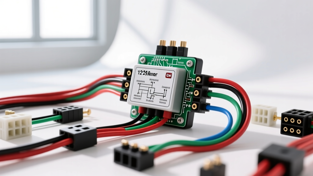
Understanding the Automotive Wiring Diagram Regulator Rectifier
When diving into vehicle electrical systems, few components are as critical—and frequently misunderstood—as the charging system's core logic. For beginners and seasoned DIYers alike, mastering the wiring diagram regulator rectifier circuit is the gateway to diagnosing dead batteries, flickering headlights, and parasitic draws. While modern vehicles often integrate these components into complex, computer-controlled LIN-bus alternators, the foundational physics and wiring principles remain identical. To provide the most practical, beginner-friendly fundamentals, this guide focuses on the gold standard of automotive charging: the classic GM 12SI internally regulated alternator. This platform perfectly illustrates how a stator, rectifier bridge, and voltage regulator interact, giving you the diagnostic skills to tackle any vehicle wiring diagram.
Core Components: Stator, Rectifier, and Regulator
Before tracing wires, you must understand the flow of electrical energy. The alternator does not 'create' electricity; it converts mechanical rotational energy into electrical current through electromagnetic induction.
The Stator and 3-Phase AC Generation
The stator consists of three distinct sets of copper windings spaced 120 degrees apart. As the magnetized rotor spins inside the stator, it induces an Alternating Current (AC). Because the windings are offset, the stator generates a '3-phase' AC waveform. However, your vehicle's battery and electrical accessories require Direct Current (DC). This is where the rectifier comes into play.
The Rectifier Bridge: Converting AC to DC
The rectifier is essentially a one-way valve system for electricity. In a standard automotive 6-diode rectifier bridge, there are three positive diodes and three negative diodes. Each of the three stator phases connects to a positive and a negative diode. When the AC waveform swings positive, the current flows through the positive diodes to the battery terminal (BAT). When the waveform swings negative, the negative diodes provide a return path to ground. This process, known as full-wave rectification, flips the negative halves of the AC sine wave into positive DC pulses, which the battery's internal capacitance smooths out into a steady DC voltage.
The Voltage Regulator: Controlling the Magnetic Field
If the alternator spun freely without regulation, highway RPMs would push system voltage well past 18 volts, boiling the battery acid and frying sensitive ECUs. The voltage regulator monitors the system voltage and adjusts the current flowing to the rotor (the electromagnet). By rapidly switching the rotor's ground path on and off—a process known as Pulse Width Modulation (PWM) or duty-cycling—the regulator strengthens or weakens the magnetic field, thereby controlling the stator's output to maintain a strict 13.8V to 14.4V window.
Decoding the GM 12SI Wiring Diagram Regulator Rectifier
The GM 12SI (System Integrated) alternator is the perfect case study for beginner wiring fundamentals. It utilizes a 2-pin connector that interfaces directly with the internal voltage regulator, alongside a heavy-gauge output stud. Below is the definitive pinout and wiring specification chart for this system.
| Terminal / Stud | Function | OEM Wire Color | AWG Size | Connection Destination |
|---|---|---|---|---|
| BAT (Output Stud) | Main DC Output to Battery | Red | 10 AWG or 8 AWG | Battery Positive (+) via Mega Fuse |
| Terminal 1 (L / Lamp) | Excitation & Dash Lamp | Brown | 18 AWG | Ignition Switch (via dash warning bulb) |
| Terminal 2 (S / Sense) | Battery Voltage Sense | Red or White | 18 AWG | Battery Positive (+) or Main Fuse Block |
| Case Ground | Alternator Ground Return | N/A (Metal Case) | N/A | Engine Block / Cylinder Head |
Why the Sense Wire Matters
Many beginners make the critical mistake of jumping Terminal 1 and Terminal 2 together right at the alternator plug. While this will make the alternator charge, it defeats the purpose of the 'Sense' wire. Terminal 2 tells the regulator what the voltage is at the battery or main distribution block. If you sense voltage at the alternator case, the regulator will not account for the voltage drop across the vehicle's wiring harness, leading to an undercharged battery. Always route the Terminal 2 sense wire directly to a clean, fused battery-positive source.
Step-by-Step Wiring and Routing Fundamentals
When building or repairing a wiring diagram regulator rectifier circuit, follow these best practices to ensure safety and longevity:
- Install a Mega Fuse: The BAT output wire (10 AWG or 8 AWG) must be protected. Install a 100A to 120A Mega fuse within 7 inches of the battery positive terminal. In the event of a crushed harness or internal diode short, this fuse prevents a catastrophic electrical fire.
- Use the Proper Connector: Never splice wires directly to the fragile spade terminals on the alternator regulator plug. Purchase a weather-pack pigtail connector with pre-crimped terminals to ensure a vibration-resistant, moisture-sealed connection.
- Verify the Excitation Circuit: Terminal 1 requires a switched 12V ignition source. However, routing this through a standard dash indicator bulb (typically a 194 or 168 bulb) provides the initial 'excitation' current needed to magnetize the rotor and start the charging process before the alternator becomes self-sustaining.
- Establish a Dedicated Ground: The alternator grounds through its mounting ears to the engine block. Paint, powder coating, and rust act as insulators. Always sand the mounting surfaces to bare metal and apply dielectric grease after torquing the bolts to spec (typically 35-50 lb-ft depending on the bracket).
Real-World Troubleshooting: Diode and Regulator Failures
Understanding the wiring diagram is only half the battle; diagnosing failures within the regulator rectifier assembly is where true expertise is built. Here is a beginner-friendly diagnostic decision tree using a standard Digital Multimeter (DMM).
Symptom: Battery Drains Overnight (Parasitic Draw)
Cause: A shorted positive diode in the rectifier bridge. When the engine is off, a failed diode allows DC current to flow backward from the battery into the stator windings, where it dissipates as heat.
The Fix: Set your DMM to Diode Test mode. Disconnect the stator wires from the rectifier. Place the red probe on the rectifier's stator pad and the black probe on the positive BAT post. A healthy diode reads 'OL' (Open Loop). If it reads a voltage drop (e.g., 0.002V), the diode is shorted and the rectifier bridge must be replaced.
Symptom: Headlights Pulse or Flicker at Idle
Cause: An open diode or worn rotor brushes. If one of the six diodes fails open, the alternator drops from a 3-phase output to a 2-phase output, causing massive AC 'ripple' voltage that the battery cannot smooth out.
The Fix: Test the AC Ripple voltage. Set your DMM to AC Volts. Place the probes on the battery terminals with the engine running and all accessories on. A healthy regulator rectifier circuit should show less than 50mV (0.050V) AC. If you see 200mV or higher, you have an open diode or a failing stator winding.
Symptom: System Overcharging (15.5V+)
Cause: A failed voltage regulator or a broken Terminal 2 sense wire. If the regulator cannot 'see' the battery voltage, it defaults to maximum field duty cycle, pushing the alternator to its absolute maximum output.
The Fix: Check the 18 AWG sense wire for continuity. If the wire is intact, the internal voltage regulator's reference circuit has failed, requiring a complete regulator/brush assembly replacement.
Authoritative References & Further Reading
To deepen your understanding of automotive charging systems and wiring schematics, consult the following industry-standard resources:
- SAE International J537 - The definitive standard for automotive battery and charging system testing, including ripple voltage and diode integrity specifications.
- Helm Incorporated (GM Service Manuals) - The authorized publisher of OEM General Motors wiring diagrams, connector pinouts, and alternator tear-down procedures.
- Painless Performance Wiring - Excellent technical bulletins on routing high-amperage charge wires, selecting proper AWG gauges, and integrating modern alternators into classic vehicle harnesses.
By mastering the fundamentals of the wiring diagram regulator rectifier circuit, you transition from simply swapping parts to truly engineering reliable, safe, and efficient vehicle electrical systems.