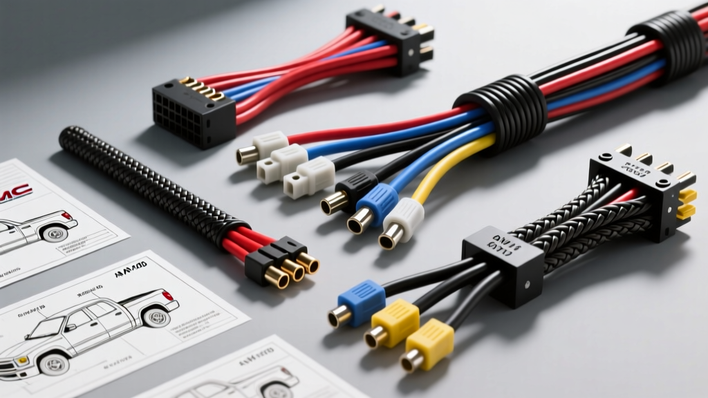
The Challenge of Navigating GMC Truck Wiring Diagrams
Whether you are restoring a classic 1978 C/K Squarebody, troubleshooting a parasitic draw on a 1996 GMT400, or performing an LS swap into a 2004 GMT800 Sierra, having the correct GMC truck wiring diagrams is non-negotiable. GM's electrical architecture evolved dramatically from the simple fused circuits of the 1970s to the complex Class 2 Serial Data and CAN-bus networks of the 2000s. Selecting the right schematic resource—and deciding whether to retain the OEM harness or upgrade to an aftermarket solution—requires a deep understanding of wire gauges, connector types, and circuit topologies.
This product comparison and selection guide evaluates the top OEM and aftermarket wiring diagram resources and harness kits, providing the technical specifications you need to make an informed decision for your GMC truck project.
OEM Factory Schematics vs. Aftermarket Harness Diagrams
When sourcing GMC truck wiring diagrams, builders generally face two distinct paths: OEM Factory Service Information or Aftermarket Universal/Restoration Harnesses. OEM diagrams are exhaustive, detailing every splice pack, diode, and resistor network. They use standardized GM color codes (e.g., Dark Green/White for fuel pump relay control) and specify exact cavity pinouts for connectors like the Delphi Metri-Pack 280 series.
Conversely, aftermarket harness kits provide simplified, color-coded diagrams designed for custom routing and modified chassis. While they sacrifice OEM-specific diagnostic depth, they offer modern wire insulation, integrated relays, and circuit breaker protection that aging factory harnesses often lack.
Product Comparison: Top Wiring Solutions for GMC Trucks
1. OEM GM Service Information (GMSIS) Diagrams
For stock restorations and deep diagnostic troubleshooting, the official GM Service Information System (or licensed equivalents like Helm Incorporated factory manuals) is the gold standard. These diagrams map the exact pinouts of the PCM/ECM.
- Best For: Stock restorations, OBD2 diagnostic troubleshooting, and CAN-bus mapping.
- Technical Depth: Includes exact wire colors (e.g., GMT800 Class 2 Data Bus is Dark Green, Pin 2 on the DLC), splice pack locations (often wrapped in friction tape behind the kick panels), and ground distribution charts (e.g., G100 and G110 engine block grounds).
- Drawback: Overwhelming for custom hot-rod builds; factory harnesses often suffer from brittle PVC insulation and capillary wicking in soldered splices.
2. Painless Performance 21-Circuit Universal Harness (Part #10102)
Painless Performance offers a universal solution that simplifies the GMC truck wiring diagrams into a straightforward, color-coded manual. This kit is heavily utilized in custom street rods and LS-swapped Squarebodies where the factory dash and PCM are being modified or relocated.
- Wire Specs: Uses SAE J1128 compliant GXL cross-linked polyethylene wire, rated for under-hood temperatures up to 125°C.
- Circuit Breakdown: Includes dedicated 12 AWG circuits for horns and headlights, 14 AWG for wipers and turn signals, and a heavy 10 AWG ignition feed.
- Connector Style: Supplied with bulkhead connectors and loose Weather-Pack terminals for custom mating to GM alternators and starters.
3. American Autowire Classic Update Series (Part #510039)
Designed specifically for 1973-1987 GMC C/K trucks, the Classic Update kit bridges the gap between OEM fitment and modern electrical demands. The included diagrams map directly to the factory fuse block location but support high-output alternators and modern EFI systems.
- Wire Specs: Upgraded 10 AWG main power feed (compared to the factory 12 AWG) to handle 100+ amp alternators.
- Diagram Style: Step-by-step, chassis-specific routing guides that mirror the original GM assembly line manuals but with modern ATO/ATM blade fuse integration.
- Headlight Circuit: Features a heavy-duty 12 AWG headlight circuit with integrated Bosch-style relays, eliminating the voltage drop common in stock GMC dimmer switches.
Technical Specification & Wire Gauge Comparison Chart
| Feature / Spec | OEM Factory Harness (GMT400/800) | Painless Performance 21-Circuit | American Autowire Classic Update |
|---|---|---|---|
| Wire Insulation | GXL / PVC (Aging) | GXL Cross-Linked | TXL / GXL Cross-Linked |
| Main Power Feed | 10 AWG to 8 AWG | 10 AWG (Fusible Link) | 10 AWG (Mega Fuse) |
| Headlight Circuit | 14 AWG (Via Dimmer Switch) | 12 AWG (Relay Triggered) | 12 AWG (Relay Triggered) |
| Diagram Complexity | High (Includes all modules/sensors) | Low (Simplified point-to-point) | Medium (Chassis specific) |
| Primary Connectors | Metri-Pack 150/280, Weather-Pack | Weather-Pack, Ring Terminals | OEM-style Bullet & Weather-Pack |
| Ideal Application | Stock Restoration / Diagnostics | Custom Chassis / LS Swaps | OEM+ Restomod / Upgrades |
How to Select the Right Diagram and Harness for Your Build
Use this decision tree to select the correct GMC truck wiring diagrams and hardware for your specific project:
- Are you retaining the factory PCM, BCM, and ABS modules?
Yes: You must use OEM GM Service Information diagrams. Aftermarket harnesses do not support the complex CAN-bus or Class 2 Serial Data networks required for GMT800 (1999-2006) and newer Sierra/Silverado trucks. You will need to repair the factory harness using Deutsch connectors and solder-seal splices. - Are you performing an LS/Vortec swap into a classic Squarebody (1973-1987)?
Yes: Select the American Autowire Classic Update kit for the chassis, and use standalone Holley/HP Tuners wiring diagrams for the engine bay. This isolates the high-current EFI demands from the vintage dash circuits. - Are you building a custom tube-chassis race truck or pro-touring C10?
Yes: The Painless Performance 21-Circuit or 24-Circuit harness is ideal. The simplified diagrams allow you to route wires through custom firewalls and chassis rails without dealing with miles of unnecessary OEM emissions and comfort wiring.
Real-World Troubleshooting: Common GMC Wiring Failure Modes
When working from GMC truck wiring diagrams, be aware of these common failure modes inherent to GM truck platforms:
The GMT800 Splice Pack Corrosion Issue
In 1999-2006 GMT800 trucks, GM utilized large, soldered splice packs wrapped in cloth friction tape, often located under the driver's side dash or behind the kick panel. Over time, condensation wicks into the tape via capillary action. This causes the Class 2 Data Bus (Dark Green wire) to short to ground, resulting in U1000 codes, erratic fuel gauges, and stalling. Fix: Cut out the factory splice pack, strip the wires, and re-splice using adhesive-lined marine heat shrink and crimp connectors.
GMT400 Grounding Degradation (G100/G110)
The 1988-1998 GMT400 relies heavily on the G100 (left front engine block) and G110 (right rear block) grounds for the ECM and fuel pump relay. If the 14 AWG Black/White ground wires show more than 0.1V of voltage drop under load, the fuel pump relay (controlled by the Dark Green/White wire) may chatter, causing lean conditions. Fix: Remove the ground bolts, clean the block mating surface to bare metal with a wire wheel, apply a thin coat of dielectric grease, and torque the hardware to 10 Nm (89 lb-in).
Tailgate Ground Loops (GMT900 Sierra)
On 2007-2013 GMT900 models, the tailgate ground wire (often Black, 16 AWG) passes through a flexible rubber boot. Repeated opening and closing fractures the copper strands, causing the backup camera to flicker or the tailgate lock actuator to fail. Always perform a continuity test on the hinge pivot wires before replacing expensive BCM modules.
Authoritative References & Further Reading
- SAE International J1128 - Standard for Low Tension Primary Cable (Wire insulation and AWG ratings for automotive use).
- Painless Performance Technical Manuals - Wiring schematics and circuit breaker sizing guides for universal harnesses.
- GM Service Repair Information - Official portal for accessing OEM GMC truck wiring diagrams, TSBs, and pinout charts.