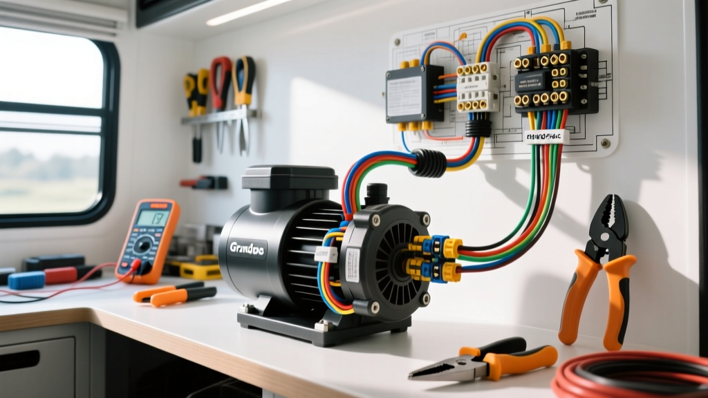
Integrating 12V DC Grundfos Pumps in Mobile Platforms
While Grundfos is globally recognized for residential and industrial fluid handling, their 12V and 24V DC brushless circulation pumps (such as the UPA 15-90 12V DC and specialized marine/RV variants) are highly prized in custom expedition vehicles, motorhomes, and mobile detailing rigs. These pumps are typically deployed for diesel hydronic heating loops, solar thermal transfer, or high-pressure water boost systems. However, adapting a stationary or marine-grade pump to a vehicle's volatile 12V/24V DC electrical architecture requires strict adherence to automotive wiring standards. This guide provides a comprehensive cost and tool requirements analysis for executing a flawless installation, utilizing the correct wiring diagram for Grundfos pump setups in mobile environments.
Analyzing the Wiring Diagram for Grundfos Pump Circuits
Unlike simple 2-wire automotive accessories, modern 12V DC Grundfos pumps often feature 3-pin or 4-pin connectors to accommodate PWM (Pulse Width Modulation) speed control and tachometer feedback. When referencing the OEM wiring diagram for Grundfos pump integration, you are typically dealing with a main power circuit, a dedicated chassis ground, and a low-current signal wire.
In a vehicle environment, the main power draw (often 1.5A to 4.0A depending on the model and head pressure) must be routed through a Bosch-style 30A/40A automotive relay or a solid-state relay (SSR) to isolate the pump's inductive kickback from the vehicle's sensitive ECU or RV house battery management system (BMS). The PWM signal wire, if utilized by a custom RV climate controller, requires a shielded cable to prevent electromagnetic interference (EMI) from alternator whine or inverter switching noise.
Pinout and Wire Color Specifications (SAE J1128 Compliant)
To maintain consistency with standard automotive and RV electrical schematics, the following wire color codes and pin configurations should be used when fabricating the custom pigtail for the pump.
| Pin | Function | SAE Wire Color | AWG Size | Connector Type |
|---|---|---|---|---|
| 1 | VCC (12V DC Power) | Red | 14 AWG | Deutsch DT - Pin 1 |
| 2 | GND (Chassis Ground) | Black | 14 AWG | Deutsch DT - Pin 2 |
| 3 | PWM Control Signal | White | 18 AWG | Deutsch DT - Pin 3 |
| 4 | Tach / Fault Output | Yellow | 18 AWG | Deutsch DT - Pin 4 |
Tool Requirements for Automotive-Grade Terminations
Mobile environments subject wiring harnesses to constant high-frequency vibration and thermal cycling. Standard hardware store crimpers and solder-only connections will fail, leading to intermittent pump operation or, worse, a high-resistance short. To properly execute the wiring diagram for Grundfos pump applications, you must invest in automotive-grade termination tools.
Essential Wiring & Crimping Tool Cost Breakdown
| Tool Category | Recommended Model | Estimated Cost | Application |
|---|---|---|---|
| Precision Wire Stripper | Knipex 12 42 195 | $75.00 | Stripping 18-10 AWG without nicking copper strands |
| Deutsch Crimper | IWISS SN-48B or HX-50B | $45.00 | Crimping solid DT/DTM contacts (12-18 AWG) |
| Heat Gun (Dual Temp) | Milwaukee M18 Compact | $149.00 | Shrinking adhesive-lined heat shrink tubing |
| Digital Multimeter | Fluke 87V Industrial | $400.00 | Testing PWM signals and millivolt voltage drops |
| Terminal Insertion Tool | Sargent Greenway 11-104 | $12.00 | Seating pins securely into Deutsch housings |
Total Baseline Tool Investment: ~$681.00. While this represents a significant upfront cost, these tools are mandatory for meeting SAE J1128 low-tension cable standards and ensuring the physical integrity of the harness in an off-road or overlanding RV build.
Material Cost Analysis and AWG Sizing
When calculating the Bill of Materials (BOM) for your Grundfos pump circuit, wire gauge must be selected based on the maximum amperage draw and the total round-trip wire length to prevent excessive voltage drop. The American Boat and Yacht Council (ABYC) E-11 standard for DC power, which is widely adopted by the high-end RV and expedition vehicle industry, dictates a maximum 3% voltage drop for critical systems.
Voltage Drop & AWG Selection Matrix
For a typical 12V Grundfos DC pump drawing 3.0A continuous current:
- Under 10 ft round-trip: 16 AWG is sufficient, but 14 AWG is recommended for mechanical durability against vibration.
- 10 ft to 20 ft round-trip: 14 AWG stranded marine wire (tinned copper) is mandatory.
- Over 20 ft round-trip: Upgrade to 12 AWG to maintain voltage at the pump terminals, ensuring the internal brushless controller does not trigger low-voltage lockout (LVLO).
Bill of Materials (BOM) & Cost Estimate
| Component | Specification | Qty | Unit Cost | Total |
|---|---|---|---|---|
| Primary Wire | Ancor Marine 14 AWG Tinned (Red/Black) | 20 ft | $0.60/ft | $12.00 |
| Signal Wire | 18 AWG Shielded (PWM) | 10 ft | $0.80/ft | $8.00 |
| Connector Kit | Deutsch DT 4-Pin Plug & Receptacle | 2 sets | $4.50 | $9.00 |
| Circuit Protection | Bussmann 5A ATC Blade Fuse + Holder | 1 | $6.50 | $6.50 |
| Relay | Bosch Style 30A SPDT (Sealed) | 1 | $8.00 | $8.00 |
| Heat Shrink | 3M Adhesive-Lined Dual Wall | 1 pack | $14.00 | $14.00 |
Total Material Cost: ~$57.50. This excludes the cost of the pump itself and the primary RV fuse block, focusing strictly on the dedicated branch circuit for the pump.
Environmental Sealing & IP67 Requirements
Vehicle underbellies, engine bays, and unheated RV basements are hostile environments characterized by moisture, road salt, and extreme temperature swings. The wiring diagram for Grundfos pump installations must account for IP67 waterproofing. Every inline splice must be sealed using adhesive-lined dual-wall heat shrink. The adhesive lining melts during the shrinking process, creating a watertight barrier that prevents capillary action from drawing moisture into the copper strands. Furthermore, the Deutsch DT connectors feature integrated silicone O-rings and secondary wedge locks, ensuring that vibration cannot back the pins out of the housing or compromise the environmental seal.
Mobile Environment Troubleshooting
Even with a perfect schematic, real-world vehicle integration presents unique electrical anomalies. Below are common failure modes encountered when integrating DC circulation pumps into automotive systems.
1. PWM Signal Interference (Alternator Whine)
Symptom: The pump speed fluctuates erratically, or the RV climate controller throws a 'Pump Fault' code when the vehicle engine is running.
Cause: EMI from the alternator or a nearby high-power inverter is inducing noise on the unshielded PWM signal wire.
Fix: Replace the standard 18 AWG signal wire with a shielded twisted-pair cable. Ground the shield drain wire at the controller end only (Pin 2 ground) to prevent ground loops, keeping the signal wire isolated from high-current 12V+ power runs.
2. Inductive Kickback Blowing Fuses
Symptom: The 5A ATC fuse blows immediately when the pump is switched off via the dashboard relay.
Cause: The pump's internal motor generates a reverse voltage spike (inductive kickback) when power is severed.
Fix: Install a 1N5408 flyback diode across the pump terminals (Pin 1 to Pin 2), with the cathode (stripe) facing the 12V+ positive supply. This provides a safe recirculation path for the voltage spike, protecting both the fuse and the switching relay contacts from arcing.
3. Intermittent Stalling Due to Voltage Drop
Symptom: Pump operates fine at idle but stalls or clicks when high-draw accessories (e.g., slide-outs, leveling jacks) are activated.
Cause: Shared ground paths or undersized AWG wiring causing a transient voltage drop below the pump's 9.5V LVLO threshold.
Fix: Run a dedicated 12 AWG ground wire directly from the pump's Deutsch connector to the house battery's negative busbar, bypassing any shared chassis ground points that may suffer from corrosion or high resistance.
By adhering to these material specifications, utilizing the proper termination tools, and strictly following the automotive-adapted wiring diagram for Grundfos pump systems, you ensure reliable, long-term fluid circulation in even the most demanding mobile platforms.