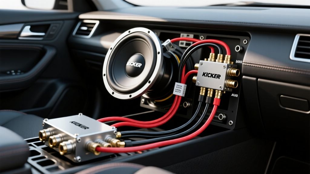
Project Overview: Integrating the Kicker L7 2-Ohm DVC
Upgrading a daily driver or dedicated build with a Kicker Solo-Baric L7 subwoofer is a milestone project in automotive audio. The L7 series, particularly the L7S and L7T lines, is legendary for its massive power handling and extreme excursion. However, feeding these subwoofers the current they demand requires more than just running a power wire and connecting an amplifier. When working with a Kicker L7 wiring diagram 2 ohm configuration, you are typically dealing with a Dual Voice Coil (DVC) 2-ohm model. This architecture offers incredible flexibility, allowing you to wire the subwoofer to either a 1-ohm or 4-ohm final load depending on your amplifier's capabilities and your vehicle's electrical system limits.
This comprehensive guide covers the exact voice coil wiring configurations, necessary vehicle electrical upgrades (including the critical 'Big 3'), proper AWG sizing, and high-current termination standards required to ensure your L7 performs flawlessly without melting your vehicle's wiring harness or triggering amplifier thermal protection.
Voice Coil Architecture: Series vs. Parallel Wiring Diagrams
A single Kicker L7 DVC 2-ohm subwoofer features four push-button or set-screw terminals: Positive A, Negative A, Positive B, and Negative B. Understanding how to manipulate these coils is the foundation of your amplifier matching strategy. According to Kicker Official Wiring Diagrams & Support, matching the subwoofer's impedance to the amplifier's optimal efficiency range is critical for maximizing the damping factor and preventing clipping.
Configuration 1: Parallel Wiring (1-Ohm Final Load)
Wiring the dual 2-ohm coils in parallel results in a 1-ohm final load. This configuration is ideal if you are using a high-output, 1-ohm stable Class D monoblock amplifier (such as the Kicker CXA1200.1 or CXA1800.1). Parallel wiring maximizes current flow, allowing the amplifier to push its maximum rated RMS wattage.
- Step 1: Run a jumper wire from the Positive A terminal to the Positive B terminal.
- Step 2: Run a jumper wire from the Negative A terminal to the Negative B terminal.
- Step 3: Connect your main amplifier positive speaker wire to either Positive terminal, and your main amplifier negative speaker wire to either Negative terminal.
- Result: 1 Ohm. (Warning: This draws massive current, often exceeding 120 Amps at full output, necessitating heavy-duty vehicle charging upgrades).
Configuration 2: Series Wiring (4-Ohm Final Load)
Wiring the coils in series doubles the impedance, resulting in a 4-ohm final load. This is the preferred method if your monoblock amplifier is only stable down to 2 ohms, or if you want to run the amplifier cooler with a higher damping factor, which yields tighter, more accurate bass transients.
- Step 1: Connect the amplifier's positive speaker wire to the Positive A terminal.
- Step 2: Run a jumper wire from the Negative A terminal to the Positive B terminal.
- Step 3: Connect the amplifier's negative speaker wire to the Negative B terminal.
- Result: 4 Ohms. This is significantly easier on the vehicle's alternator and reduces heat dissipation in the amplifier's output stage.
Vehicle Electrical System Prep: The High-Current Big 3 Upgrade
Before finalizing your Kicker L7 wiring diagram 2 ohm setup, you must address the vehicle's electrical bottleneck. Factory wiring is designed for stock electrical loads, typically utilizing 4 AWG to 6 AWG wire for the main charging circuit. Pushing a 1500W+ L7 system will cause severe voltage drop, resulting in dimming headlights, alternator whine, and amplifier protect-mode shutdowns.
Following SAE J2202 Heavy Duty Wiring Systems Standards, high-current automotive circuits require upgraded conductors to minimize resistance and voltage drop over the length of the run. The 'Big 3' upgrade replaces or supplements the three main current paths in the engine bay:
- Alternator Positive to Battery Positive: Upgrading this path allows the alternator to deliver maximum current to the battery and amplifier without bottlenecking at the factory harness.
- Engine Block to Chassis Ground: The engine block is the primary ground for the alternator casing. A poor ground here restricts total system output.
- Battery Negative to Chassis Ground: This completes the circuit back to the vehicle's body, where your amplifier's ground strap will be anchored.
AWG Wire Sizing, Fusing, and Termination Specifications
When selecting wire for a Kicker L7 upgrade, you must strictly use Oxygen-Free Copper (OFC). Copper-Clad Aluminum (CCA) wire has roughly 40% less conductivity and is prone to oxidizing and snapping under high-vibration environments. The CTA Mobile Electronics Installation Standards dictate strict AWG sizing based on current draw and run length.
| Circuit Path | Recommended Wire (OFC) | Terminal Type | Fusing / Torque Specs |
|---|---|---|---|
| Main Power (Battery to Amp) | 1/0 AWG or 0 AWG OFC | ANL Fuse Holder, Tinned Ring | 250A ANL within 18in of battery |
| Big 3 Upgrade Runs | 0 AWG OFC | 5/16' or M8 Ring Terminal | 22 lb-ft torque on chassis bolts |
| Amplifier Ground | 0 AWG OFC | M8 Ring to Bare Metal | Sand to bare metal, apply dielectric grease |
| Remote Turn-On Lead | 18 AWG Primary Wire | Spade / Butt Connector | 5A Inline ATC Fuse at source |
| Speaker Wire (Amp to L7) | 12 AWG OFC | Banana Plugs or Ferrules | N/A (Keep away from RCA signal cables) |
Amplifier to Subwoofer Routing & Signal Integrity
When wiring a 2-ohm DVC L7, the speaker wire gauge is just as critical as the power wire. Many installers mistakenly use 16 AWG speaker wire, but at 1000+ Watts RMS, the resistance of thin wire alters the damping factor, making the L7's massive motor structure feel 'loose' and resulting in muddy bass response. Always use a minimum of 12 AWG OFC speaker wire.
Termination Best Practices: If your Kicker L7 features set-screw terminals, do not simply strip the wire and jam it under the screw. The strands will fray, causing short circuits against the adjacent terminal or the subwoofer basket. Instead, crimp a 12 AWG pin ferrule onto the wire using a specialized hex-crimp tool, then insert the ferrule into the set-screw terminal. If your L7 model uses push-button spring terminals, tin the ends of the 12 AWG wire with a high-wattage soldering iron to create a solid, unified conductor before inserting it into the terminal block.
Signal Routing: Run your RCA signal cables down the driver's side of the vehicle, and run your 0 AWG power wire and 12 AWG speaker wires down the passenger side. Crossing high-current power cables with low-voltage RCA cables induces electromagnetic interference (EMI), manifesting as alternator whine that scales with engine RPM.
Diagnostic Troubleshooting: High-Current Failure Modes
Even with a perfect Kicker L7 wiring diagram 2 ohm layout, high-current systems can exhibit specific failure modes. Use a Digital Multimeter (DMM) to diagnose the following issues:
- Amp Protect Light Flashing on Heavy Bass Hits: This is rarely a thermal issue; it is almost always voltage drop. Set your DMM to DC Volts. Place the red probe on the amplifier's positive power terminal and the black probe on the amplifier's ground terminal. Play a 40Hz sine wave at high volume. If the voltage drops below 10.5V, your vehicle's charging system is failing, or your ground connection has excessive resistance. Sand the ground point to bare metal and retorque to 22 lb-ft.
- Subwoofer Chuffing or Mechanical Bottoming: If the L7 is making mechanical clunking noises, check your series/parallel jumper wires. A loose jumper wire on one voice coil will force the amplifier to push all current through a single 2-ohm coil while the other coil acts as a passive radiator. This unbalanced electrical force will rapidly destroy the subwoofer's spider and tinsel leads.
- Amplifier Getting Excessively Hot (Thermal Protect): If you are wiring the L7 to a 1-ohm load, ensure the amplifier has adequate airflow. Class D amplifiers operating at 1 ohm generate significant heat in the output filter inductors. Ensure the amplifier is not mounted in a sealed, carpeted enclosure without ventilation.
Authoritative References & Standards
For further technical validation, always consult the specific manual for your L7 generation (L7, L7S, or L7T), as terminal styles and RMS ratings vary slightly by year. Adhering to Kicker Official Wiring Diagrams, SAE J2202 Wiring Standards, and CTA Installation Guidelines ensures your upgrade project delivers concert-level SPL safely and reliably for years to come.