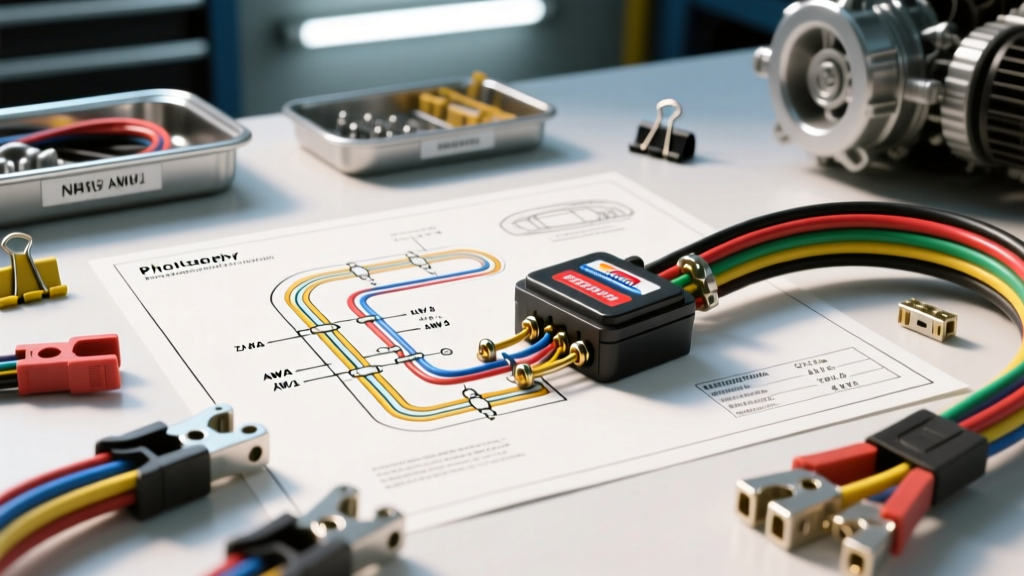
Understanding the Wiring Diagram Battery Kill Switch Install
Executing a flawless wiring diagram battery kill switch install is one of the most critical safety upgrades for any track-prepped or high-performance street vehicle. Whether you are building a dedicated drag car, a time-attack racer, or simply looking to eliminate parasitic draw on a garage queen, understanding the complete circuit topology is mandatory. A master disconnect switch does not merely sever the connection to the starter; in modern fuel-injected vehicles, it must also safely manage the alternator's magnetic field to prevent catastrophic voltage spikes that can instantly fry the ECU, PCM, and sensitive sensor networks. In this complete wiring diagram walkthrough, we will dissect the exact AWG requirements, NHRA-compliant routing protocols, and the crucial alternator exciter interrupt circuit.
NHRA Compliance and the Alternator Dilemma
According to the official NHRA Rulebook, any vehicle with a relocated battery or a dedicated racing setup must feature an external master cutoff switch. The rule explicitly states that the switch must be capable of stopping all electrical functions, including the engine. This is where amateur builders fail. If you only sever the main battery cable, the alternator will continue to self-excite, keeping the engine running and potentially spiking system voltage well past 100 volts when the battery (the system's primary capacitor and buffer) is removed from the circuit. To comply with SAE J1128 standards and NHRA safety tech inspections, your wiring diagram must incorporate a Double-Pole, Single-Throw (DPST) switch topology.
Single-Pole vs. Double-Pole (DPST) Switch Topologies
A standard Single-Pole switch only interrupts the main battery feed. While this works for carbureted vehicles with no alternator (or a one-wire alternator that requires high RPM to self-excite), it is entirely unsafe for modern EFI vehicles. A DPST switch features four main terminals: two large studs for the main battery cables (1/0 AWG) and two smaller spades or studs for the alternator exciter circuit (12 AWG). When you rotate the handle to the OFF position, both the main starter feed and the alternator's field excitation are severed simultaneously, ensuring the engine dies immediately and safely.
Master Specification Chart: Wire Gauges and Hardware
Before cutting into your vehicle's harness, ensure you have the correct materials. Using undersized wire or stamped terminals will result in high resistance, voltage drop, and potentially a fire under heavy cranking loads.
| Circuit Segment | Wire Gauge (AWG) | Conductor Material | Terminal Type | Torque Spec |
|---|---|---|---|---|
| Main Battery to Switch | 1/0 AWG | Tinned Copper | 3/8" Ring Terminal | 12-15 ft-lbs |
| Switch to Starter/Solenoid | 1/0 AWG | Tinned Copper | 3/8" Ring Terminal | 12-15 ft-lbs |
| Alternator Exciter Feed | 12 AWG | Stranded Copper | Spade / Bullet | N/A (Crimp) |
| Switch Mounting Hardware | N/A | Stainless Steel | 1/4" Bolts | 8 ft-lbs |
Complete Wiring Diagram Walkthrough: Phase 1 (Main Power)
The first phase of the wiring diagram battery kill switch install involves the high-amperage main cables. Always begin by disconnecting the negative battery terminal and waiting 15 minutes for the ECU capacitors to discharge. For NHRA compliance, the main cutoff is typically installed on the positive side of the battery, though negative-side cutoffs are permitted if they completely isolate the vehicle's electrical system and include the alternator kill.
Route a 1/0 AWG tinned copper cable from the positive battery post to the large input stud on the DPST switch. From the opposing large output stud, route a second 1/0 AWG cable directly to the starter solenoid or the main distribution block. Critical Step: Do not use a hammer or pliers to crimp 1/0 AWG terminals. You must use a hydraulic crimper to ensure a cold-weld connection. After crimping, seal the terminal with 3/8" adhesive-lined marine heat shrink to prevent moisture intrusion and galvanic corrosion, which is a leading cause of hidden voltage drops.
Phase 2: Interrupting the Alternator Exciter Circuit
This is the most misunderstood portion of the diagram. The alternator requires a small 12V signal to energize the rotor's magnetic field. On a GM CS130 alternator, this is the 'L' terminal on the 4-pin pigtail. On a Ford 3G alternator, it is the 'I' (Ignition) terminal. You must locate this specific exciter wire (usually 14 to 12 AWG, often white, red, or yellow depending on the OEM harness) and route it through the smaller secondary poles on your DPST switch.
When the switch is turned ON, 12V flows from the ignition switch, through the DPST secondary contacts, and into the alternator exciter pin, allowing the alternator to charge. When the switch is turned OFF, this circuit is broken, the magnetic field is starved of current, and the alternator stops producing power, allowing the engine to stall safely.
Phase 3: Flyback Diode and Resistor Integration
Severing the alternator exciter wire while the engine is at high RPM introduces a severe hazard: inductive kickback. According to Lenz's Law, the sudden collapse of the magnetic field inside the alternator rotor generates a massive reverse voltage spike. Without a bleed path, this spike will arc across the internal contacts of your kill switch, eventually welding them shut, or worse, travel backward into the wiring harness and destroy the ECU's internal voltage regulator.
To prevent this, your wiring diagram must include a bleed circuit wired in parallel across the secondary (exciter) terminals of the DPST switch. You have two options:
- Option A (Resistor): Wire a 50-ohm, 10-watt ceramic power resistor across the two small switch terminals. This provides a controlled decay path for the magnetic field.
- Option B (Flyback Diode): Wire a 1N5408 (3-Amp) flyback diode across the terminals. The cathode (striped end) must face the 12V ignition feed side, blocking current during normal operation but allowing the reverse spike to recirculate and dissipate safely when the switch is opened.
Real-World Failure Modes and Troubleshooting
Even with a perfect diagram, physical installation errors can cause systemic failures. Use this diagnostic tree if your setup fails tech inspection or bench testing:
- Symptom: Engine continues to run after the switch is flipped to OFF.
Cause: Alternator backfeeding through the dash warning light circuit or a secondary ECU ignition feed.
Fix: Verify the DPST switch is correctly interrupting the specific alternator exciter terminal (e.g., GM 'L' terminal), not just the main output stud or a generic ignition wire. - Symptom: Melted switch casing, discolored copper, or a burning smell under heavy cranking.
Cause: High resistance connection due to improper crimping, undersized wire (e.g., using 2 AWG instead of 1/0 AWG on a 200A+ system), or loose hardware.
Fix: Cut back damaged wire, use a hydraulic crimper for 1/0 AWG terminals, and torque the 3/8" copper stud nuts to exactly 12-15 ft-lbs. Over-torquing can snap the stud; under-torquing causes arcing. - Symptom: Blown ECU, PCM, or dashboard gauges immediately upon switching OFF at high RPM.
Cause: Inductive voltage spike from the alternator rotor field collapse lacking a bleed path.
Fix: Install the aforementioned 50-ohm 10W resistor or 1N5408 flyback diode across the exciter switch terminals to absorb the kinetic energy.
Authoritative References and Component Sourcing
For further technical validation and component sourcing, refer to the following automotive electrical resources:
- NHRA Official Rulebook - Section 8: Electrical and Battery Relocation Requirements.
- SAE International J1128 - Low Tension Primary Cable specifications for high-heat automotive environments.
- Flaming River Industries - Manufacturer documentation for marine-rated DPST master disconnect switches and alternator kill relays.
By adhering strictly to this wiring diagram battery kill switch install walkthrough, you ensure your vehicle meets the highest safety standards while protecting thousands of dollars in sensitive EFI and ECU components from catastrophic electrical failure.