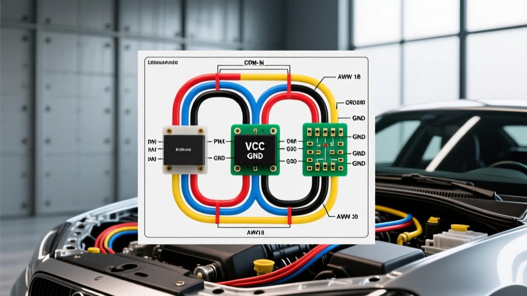
Advanced Architecture: The 3-Port Boost Control Solenoid
In modern forced-induction engine management systems, precise pneumatic control is paramount. While early turbocharged vehicles relied on simple 2-port bleed valves to manipulate wastegate pressure, advanced platforms utilize a 3-port electronic boost control solenoid (EBCS). Understanding the wiring diagram 3 port valve architecture is critical for automotive electrical technicians, as these components operate under high-frequency Pulse Width Modulation (PWM) and present significant inductive loads to the Engine Control Unit (ECU).
Unlike a 2-port valve that simply bleeds pressure to the atmosphere, a 3-port valve features a Common (COM) port, a Normally Open (NO) port, and a Normally Closed (NC) port. This interrupt-style routing allows the ECU to completely block compressor discharge pressure from reaching the wastegate actuator at peak duty cycles, yielding vastly superior boost targeting and transient response. However, this rapid pneumatic switching requires an equally robust and precise electrical circuit.
The Role of the PWM Low-Side Driver
The ECU controls the 3-port valve using a low-side PWM driver. The solenoid is constantly supplied with switched 12V+ battery voltage. The ECU completes the circuit to ground, pulsing the connection on and off at a specific frequency (typically 30Hz to 50Hz) and duty cycle (0% to 100%). Because the solenoid coil is fundamentally an inductor, the wiring harness and ECU driver must be engineered to handle severe electromagnetic forces and voltage transients.
OEM Wiring Diagram: 3 Port Valve Pinout & Routing
Below is the standard OEM pinout configuration for a high-performance 3-port boost control solenoid, commonly found in Subaru EJ/FA series, Mitsubishi 4G63/4B11, and modern Ford EcoBoost applications. The circuit relies on a dedicated power feed from the main EFI relay and a dedicated PWM ground return to the ECU.
| Pin / Circuit | Function | Wire Color (Typical OEM) | AWG Size | Destination |
|---|---|---|---|---|
| Pin 1 (B+) | Switched +12V Power | Red / White Tracer | 16 AWG | EFI Main Relay (Fused 15A) |
| Pin 2 (PWM) | Low-Side ECU Driver | Green / Yellow Tracer | 18 AWG | ECU Pin (e.g., B134 Pin 12) |
| N/A (Parallel) | Flyback Clamping Diode | Integrated in Pigtail | N/A | Across Pins 1 & 2 (Reverse Bias) |
Note: Always verify specific pinouts against the factory service manual for your exact vehicle make, model, and year, as ECU connector cavity numbers vary by manufacturer.
Wire Gauge, Connector Specs, and Harness Routing
The physical wiring harness for a 3-port valve must withstand extreme under-hood temperatures (often exceeding 120°C / 248°F near the turbocharger housing) and high-frequency vibration. OEM manufacturers utilize cross-linked polyethylene (XLPE) or Tefzel (ETFE) insulated wiring.
- Connector Type: Sumitomo HM 090 Series 2-Way or Bosch EV1 Sealed Connector.
- Terminal Material: Tin-plated copper alloy with silicone cavity seals and a rear wire seal mat.
- Harness Routing: The harness must be routed away from the exhaust manifold and turbocharger center housing. If the wiring must cross a high-heat zone, it requires a fiberglass or basalt heat sleeve. Furthermore, the PWM control wire should not be bundled parallel to high-current injector circuits to prevent cross-talk and electromagnetic interference (EMI).
The Physics of Inductive Kickback & Flyback Protection
The most critical, yet frequently overlooked, aspect of the wiring diagram 3 port valve circuit is the flyback (clamping) diode. When the ECU's internal transistor grounds the circuit, current flows through the solenoid coil, building a magnetic field that moves the internal plunger. When the ECU opens the transistor to pulse the circuit off, the magnetic field collapses rapidly.
According to Faraday's Law of Induction, this rapid collapse generates a massive reverse voltage spike (V = -L * di/dt). Without a clamping diode, this inductive kickback can exceed 80 to 100 volts. This spike will travel directly back into the ECU, eventually punching through the silicon junction of the ECU's low-side MOSFET or Darlington transistor, resulting in a permanently shorted ECU driver and a solenoid that remains stuck open (causing severe overboost and potential engine failure).
The Fix: A 1N4004 or high-speed Schottky diode must be installed in parallel with the solenoid coil, oriented in reverse bias (cathode to +12V, anode to ECU PWM). Many premium OEM and aftermarket 3-port valves feature this diode integrated directly into the connector mold. If you are fabricating a custom harness or replacing a pigtail, you must solder a diode into the circuit.
Advanced Troubleshooting: Oscilloscope Diagnostics
Multimeters are insufficient for diagnosing high-frequency PWM circuits. To properly evaluate the health of the 3-port valve and its wiring, an automotive oscilloscope (such as a PicoScope) is required. As detailed in the PicoScope Automotive Waveform Library, analyzing the voltage trace reveals the exact state of the circuit.
Step-by-Step Scope Procedure
- Channel A (Power Feed): Back-probe Pin 1 (+12V). With the engine running, you should see a clean, flat DC line at approximately 13.8V to 14.2V (alternator charging voltage). Any voltage drop below 13.0V indicates high resistance in the EFI relay circuit or a failing main fuse.
- Channel B (PWM Control): Back-probe Pin 2 (ECU Ground). Set your scope to capture a square wave. At idle (low boost demand), the duty cycle will be low. Under wide-open throttle (WOT), the duty cycle will approach 80-95%.
- Analyze the Inductive Spike: Zoom in on the exact moment the square wave transitions from Low (0V) to High (Open Circuit). A healthy circuit with a functioning flyback diode will show a sharp rise to roughly 14.5V, followed by a smooth, exponential decay curve. If you see violent "ringing" or voltage spikes exceeding 40V, the flyback diode has failed or is missing, and the ECU driver is in imminent danger.
ECU PWM Frequency Tuning and Duty Cycle Mapping
When integrating aftermarket 3-port valves or tuning standalone ECUs (e.g., MoTeC, Haltech, Syvecs), selecting the correct PWM frequency is vital. The mechanical mass of the 3-port valve plunger dictates its resonant frequency.
- Low Frequency (10Hz - 20Hz): Causes audible valve chatter and pneumatic hysteresis. The wastegate actuator will pulse in sync with the solenoid, leading to unstable boost traces and surging.
- Optimal Frequency (30Hz - 50Hz): The industry standard for most OEM and aftermarket 3-port valves (e.g., MAC Valves 35 series). This frequency is fast enough to average out the pneumatic pressure into a smooth, continuous signal, but slow enough to prevent excessive heat buildup in the solenoid coil.
- High Frequency (100Hz+): While it provides ultra-smooth pneumatic control, high frequencies cause the solenoid coil to generate immense heat due to eddy currents and hysteresis losses in the iron core. Furthermore, high-frequency PWM wiring acts as an antenna, broadcasting EMI that can interfere with sensitive CAN bus networks or wideband O2 sensor controllers, violating SAE J1113 Electromagnetic Compatibility standards.
Real-World Failure Modes and Harness Repair
When diagnosing boost control solenoid codes (e.g., P0033, P0034, or manufacturer-specific EBCS circuit codes), technicians frequently misdiagnose a failed solenoid when the root cause lies in the wiring harness. Common failure modes include:
- Heat Soak Resistance Drift: As the 3-port valve is heat-soaked by the turbocharger, the copper coil's resistance increases. A valve that measures 22 Ohms cold may rise to 35 Ohms hot. The ECU's current-limiting protection may interpret this high-resistance state as an open circuit, triggering a soft limp-mode code. Always measure resistance at operating temperature.
- Connector Fretting Corrosion: Engine vibration causes microscopic movement between the male and female terminals in the Sumitomo connector. This fretting wears away the tin plating, leading to oxidation and intermittent PWM signal loss. Repair requires extracting the terminals, cleaning with electronic contact cleaner, and applying dielectric grease (e.g., Nyogel 760G) before reseating.
- Firewall Bulkhead Chafing: The wiring harness often passes through a rubber grommet at the firewall. Over time, engine torque roll can cause the harness to rub against the sheet metal, wearing through the XLPE insulation and shorting the PWM wire to the chassis ground. This results in a 100% duty cycle (full boost) and immediate overboost protection intervention by the ECU.
By mastering the electrical theory, PWM diagnostics, and physical harness requirements of the 3-port boost control valve, technicians can ensure reliable, high-performance forced induction operation while protecting expensive ECU hardware from catastrophic inductive failures.