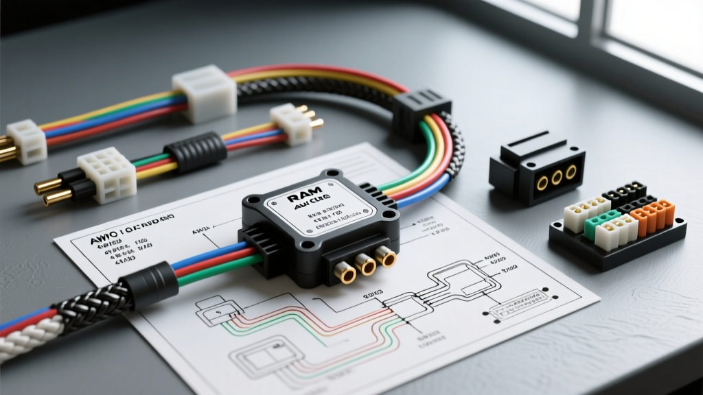
Architecture of the Ram HD Upfitter System
Integrating aftermarket accessories into late-model Ram 2500 and 3500 Heavy Duty trucks requires a thorough understanding of the factory Body Control Module (BCM) and Power Distribution Center (PDC) architecture. Unlike older vehicles where auxiliary switches were simple mechanical pass-throughs, the modern Ram aux switch wiring diagram relies on a sophisticated, BCM-monitored solid-state relay network. When you press an overhead upfitter switch, a LIN-bus (Local Interconnect Network) signal is sent to the BCM, which then grounds the coil of a dedicated high-amperage relay located in the under-hood PDC. This design protects the cabin wiring from high current loads but introduces specific constraints regarding inrush current and voltage drop that off-road builders and fleet upfitters must respect.
This advanced technical deep dive covers the exact blunt-cut wire locations, factory amperage ratings, relay integration logic, and SAE-compliant wire gauge requirements for the 2019-2024 Ram HD upfitter interface. Whether you are wiring a 12,000-lb winch contactor, a high-draw LED light bar array, or onboard air compressors, bypassing the factory engineering parameters will result in BCM fault codes or thermal shutdowns.
Factory Aux Switch Load Ratings & Wire Mapping
The Ram HD overhead console features six auxiliary switches, each mapped to a dedicated fuse and relay in the engine compartment PDC. The blunt-cut pigtail wires are pre-terminated by the factory and bundled in a black corrugated loom. Below is the definitive mapping for the upfitter interface. Note that while Mopar uses specific wire insulation colors, every wire features a printed alphanumeric tag near the cut end for positive identification.
| Switch ID | Max Rating | Wire Color (Typical) | Tag ID | AWG Size | Primary Use Case |
|---|---|---|---|---|---|
| Aux 1 | 40A | Dark Green | AUX 1 | 10 AWG | Winch Solenoids, Air Compressors |
| Aux 2 | 40A | Light Green | AUX 2 | 10 AWG | High-Draw Lighting Arrays |
| Aux 3 | 30A | Yellow | AUX 3 | 12 AWG | Amplifiers, Cooling Fans |
| Aux 4 | 30A | Brown | AUX 4 | 12 AWG | Work Lights, Tool Boxes |
| Aux 5 | 15A | Gray | AUX 5 | 16 AWG | Relay Triggers, Solenoid Valves |
| Aux 6 | 15A | Purple | AUX 6 | 16 AWG | Low-Draw Logic Triggers |
Disclaimer: Always verify the physical tag on the wire and consult the specific model-year Ram Body Builder's Guide, as PDC revisions occur mid-generation.
Physical Routing & Blunt-Cut Termination
Under-Hood PDC Interface Location
On 2019 and newer Ram 2500/3500 models, the upfitter blunt-cut wires are located in the engine compartment on the passenger side. Trace the main chassis harness from the firewall toward the PDC. You will find a secondary loom taped to the primary harness, terminating in six blunt-cut wires. These wires are switched +12V outputs. They do not provide a ground; they provide battery voltage only when the corresponding overhead switch is activated and the ignition is in the RUN or ACC position.
Termination Best Practices: Never use standard vinyl electrical tape or crimp-only butt connectors under the hood. The engine bay environment subjects connections to extreme thermal cycling and moisture. You must use marine-grade, dual-wall heat shrink butt connectors (such as Ancor or 3M) with an internal polyamide adhesive lining. When heated, the adhesive melts and seals the connection, preventing galvanic corrosion and copper oxidation, which are the leading causes of voltage drop in upfitter circuits.
Advanced Relay Integration for High-Draw Accessories
A common and catastrophic mistake made by amateur installers is wiring a 40A LED light bar directly to the 40A Aux 1 or Aux 2 blunt-cut wire. While the steady-state draw of the light bar may only be 25A, LED drivers contain large capacitors that create a massive inrush current (sometimes exceeding 80A for a few milliseconds) upon startup. The Ram BCM monitors current draw at the microsecond level. If it detects an inrush spike that exceeds the safety threshold, it will interpret the event as a short circuit and instantly shut down the circuit, requiring an ignition cycle or OBD2 scan tool to reset the BCM logic.
Wiring a High-Inrush LED Light Bar via Secondary Relay
To protect the factory BCM while utilizing the overhead switches, use the aux switch to trigger a secondary, high-quality automotive relay (e.g., Bosch-style ISO mini relay, 40A/50A rated).
- Control Circuit (Coil): Connect the Aux 5 (15A, Gray) or Aux 6 (15A, Purple) blunt-cut wire to Pin 86 of your secondary relay. Connect Pin 85 to a clean, bare-metal chassis ground. Sand away paint and use a star washer to ensure < 0.5 ohms of resistance.
- Load Circuit (Contacts): Run a dedicated 8 AWG power wire from the PDC battery stud (or a dedicated busbar) through a manual reset circuit breaker or ANL fuse directly to Pin 30 of the relay.
- Accessory Output: Connect Pin 87 of the relay to the positive input of your LED light bar. Ground the light bar directly to the chassis or battery negative.
This configuration ensures the BCM only sees the negligible 150mA draw of the relay coil, completely isolating the factory upfitter wiring diagram from the high inrush current of the accessory.
AWG Sizing & Voltage Drop Mitigation
When extending the factory blunt-cut wires to the front bumper, bed, or rear of the truck, voltage drop becomes a critical factor. According to SAE J1128 standards for low-tension primary cable, copper wire resistance increases with length, leading to diminished performance at the accessory and excess heat generation in the wire insulation. Use the following chart to select the correct extension wire gauge based on the total round-trip circuit length (positive + ground).
| Circuit Length (Round Trip) | 15A Load (Aux 5/6) | 30A Load (Aux 3/4) | 40A Load (Aux 1/2) |
|---|---|---|---|
| Under 10 Feet | 16 AWG | 10 AWG | 8 AWG |
| 10 - 20 Feet | 14 AWG | 8 AWG | 6 AWG |
| 20 - 40 Feet | 12 AWG | 6 AWG | 4 AWG |
| Over 40 Feet | 10 AWG | 4 AWG | 2 AWG |
Note: Always use SAE-rated GXL or TXL cross-linked polyethylene (XLPE) insulated wire for under-hood and chassis routing. Standard PVC-insulated THHN wire from hardware stores will melt against exhaust components and degrade rapidly from under-hood UV and chemical exposure.
Diagnostic Decision Tree: Switch Illuminates, Accessory Fails
When troubleshooting a Ram aux switch circuit where the overhead LED indicator turns on, but the accessory receives no power, follow this diagnostic sequence using a digital multimeter (DMM):
- Step 1: Verify Blunt-Cut Voltage. Set DMM to DC Volts. Probe the blunt-cut wire and a known good engine ground. If you read 12.5V+ with the switch ON, the BCM, PDC relay, and factory wiring are functioning perfectly. The fault lies in your aftermarket extension or accessory. Proceed to Step 2.
- Step 2: Check for Voltage Drop Across Extensions. Keep the switch ON. Probe the accessory end of your extended wire. If voltage reads below 11.0V, you have undersized wire, a corroded butt connector, or a poor ground. Perform a voltage drop test across each connection point (should read < 0.1V per connection).
- Step 3: Verify Accessory Ground. A common failure mode is relying on painted body panels for grounds. Measure resistance between the accessory ground lug and the negative battery terminal. It must read < 0.5 ohms. If higher, run a dedicated ground wire or sand the chassis contact point to bare metal.
- Step 4: BCM Thermal/Short Protection. If the blunt-cut wire reads 0V despite the overhead switch illuminating, the BCM may have tripped its internal solid-state protection due to a previous short or inrush spike. Turn the ignition OFF, remove the key/fob for 60 seconds to allow the BCM to sleep and reset, then retest. If it still reads 0V, check the corresponding high-amp fuse in the PDC.
References & Authoritative Sources
For exact pinouts, torque specifications (e.g., 11 Nm / 97 in-lbs for M8 PDC ring terminals), and generation-specific revisions, always cross-reference your build with the official Ram Body Builder's Guide. Additional upfitter schematics and LIN-bus logic diagrams can be sourced through the Mopar Connections Upfitter Portal. Wire insulation and gauge specifications referenced in this guide adhere to SAE J1128 Low Tension Primary Cable standards.