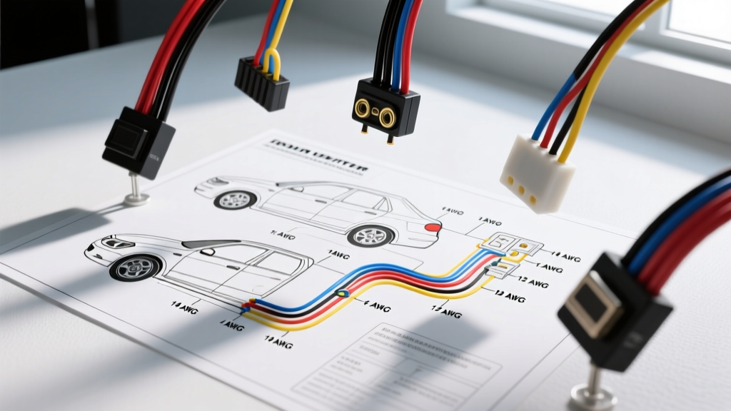
Decoding the Ram Upfitter Wiring Diagram
Ram Heavy Duty trucks (specifically the 2014-2018 2500 and 3500 platforms) are renowned for their factory-integrated auxiliary upfitter switches. These switches are designed to eliminate the need for drilling into your dashboard or running sketchy toggle switches across your steering column. However, properly utilizing the Ram upfitter wiring diagram requires more than just splicing into a random wire under the hood. The factory provides a dedicated blunt-cut harness, but integrating it safely with high-draw aftermarket accessories—such as LED light bars, air compressors, or winch solenoids—demands a strict adherence to automotive electrical standards.
Unlike older vehicles where you had to source a switched 12V+ ignition signal, the Ram upfitter system utilizes a dedicated control module located in the Power Distribution Center (PDC). When you press a switch on the overhead console or steering wheel, the module energizes a specific blunt-cut wire under the hood. This wire acts as a +12V trigger signal, which is already fused and relayed by the truck's computer. Your primary task is to use this trigger signal to activate the coil of your accessory's secondary relay.
Upfitter Wire Color Codes and Amperage Specifications
Locating the upfitter harness is the first hurdle. In the 4th-generation Ram HD, the blunt-cut wires are typically found under the hood, near the driver's side battery or tucked behind the main firewall grommet. They are wrapped in corrugated split loom and black foam tape, often secured with a zip tie to the main chassis harness. Before making any cuts, verify the wire colors and gauge sizes against the specification table below.
| Switch ID | Wire Color Code | Wire Gauge (AWG) | Max Amperage Rating | Recommended Application |
|---|---|---|---|---|
| Aux 1 | Violet / Yellow (VIO/YEL) | 12 AWG | 30 Amps | High-draw LED light bars, winch relays |
| Aux 2 | Violet / Light Green (VIO/LT GRN) | 12 AWG | 30 Amps | Off-road lighting, air compressor triggers |
| Aux 3 | Violet / White (VIO/WHT) | 12 AWG | 30 Amps | Amber strobes, work lights |
| Aux 4 | Violet / Orange (VIO/ORG) | 12 AWG | 30 Amps | Backup cameras, secondary fuel pumps |
| Aux 5 | Violet / Brown (VIO/BRN) | 14 AWG | 20 Amps | Interior accessory power, CB radios |
| Aux 6 | Violet / Gray (VIO/GRY) | 14 AWG | 20 Amps | Low-draw indicators, solenoid triggers |
Note: Always cross-reference your specific VIN with the Ram Body Builder's Guide to account for mid-year production variances and CAN-bus module updates.
Step-by-Step Auxiliary Switch Installation Guide
Executing a reliable, rattle-free, and electrically sound installation requires the right tools and methodology. Follow these steps to properly interface your Ram upfitter wires with aftermarket accessories.
Step 1: Safety and Preparation
Disconnect the negative battery terminal to prevent accidental short circuits while working near the PDC and main firewall grommets. Gather your tools: a ratcheting wire crimper (not standard pliers), a digital multimeter, wire strippers, and marine-grade adhesive-lined heat shrink tubing. Adhesive heat shrink is mandatory for under-hood applications to prevent moisture ingress and copper oxidation, aligning with SAE J1128 Low Tension Primary Cable standards for environmental resistance.
Step 2: Locate and Verify the Trigger Signal
Unwrap the foam tape securing the blunt-cut upfitter wires. Using a multimeter set to DC Voltage, reconnect the battery temporarily (or use a memory saver). Turn the ignition to the RUN position and press Aux 1. Probe the Violet/Yellow wire. You should read 12.2V to 12.6V. Once verified, disconnect the battery again and label the wire with heat-shrink marker tubing.
Step 3: Routing Through the Firewall
Do not pierce the main firewall grommet with a screwdriver or drill. Locate the secondary rubber grommet near the brake booster or the main harness pass-through. Use a fiberglass fish tape or a stiff piece of 14 AWG wire wrapped in electrical tape to gently push through the rubber nipple. Pull your accessory's relay trigger wire through the firewall, ensuring it has a drip loop to prevent water from tracking down the wire into the cabin.
Step 4: Splicing and Termination
Strip 3/16" of insulation from the Ram upfitter wire and your relay trigger wire. Use a closed-barrel, nylon-insulated butt connector sized for 12-10 AWG (yellow). Crimp using a ratcheting crimper to ensure the copper strands are compressed to a gas-tight seal. Apply 3:1 shrink ratio adhesive heat shrink over the crimp, heating from the center outward until the adhesive seals the edges.
Integrating a Standard 5-Pin ISO Relay
The Ram upfitter wire provides a +12V trigger, but it should never carry the full load of a high-draw accessory. Running 15 amps of LED lighting directly through the 12 AWG upfitter wire over a long distance will cause severe voltage drop and potentially overheat the factory PDC module. You must use the upfitter wire to trigger Pin 86 of a standard Bosch-style 5-pin ISO relay.
| Relay Pin | Function | Connection Source | Wire Gauge Required |
|---|---|---|---|
| 85 | Coil Ground | Direct to Vehicle Chassis or Battery (-) | 14 AWG |
| 86 | Coil Trigger (+12V) | Ram Upfitter Wire (e.g., VIO/YEL) | 14 AWG |
| 30 | Common (Load Input) | Direct to Battery (+) via Inline Fuse | 10 AWG or 8 AWG |
| 87 | Normally Open (Load Output) | Accessory Positive (+) Wire | 10 AWG or 8 AWG |
| 87a | Normally Closed | Not Used (Tape and Secure) | N/A |
For a comprehensive breakdown of relay coil suppression and diode integration to protect the Ram TIPM/PDC from inductive voltage spikes, refer to the Littelfuse Relay Application Guide.
Real-World Troubleshooting and Voltage Drop Testing
Even with a flawless wiring diagram, aftermarket installations frequently encounter electrical gremlins. Use this diagnostic decision tree to resolve common Ram upfitter issues.
Symptom: Accessory Does Not Power On When Switch is Pressed
- Cause 1: Blown Upfitter Fuse. The Ram PDC contains dedicated fuses for the upfitter module. If you accidentally grounded the Violet/Yellow wire during installation, the factory fuse is likely blown. Check the PDC diagram on the underside of the fuse box cover.
- Cause 2: Poor Relay Coil Ground. Pin 85 must have a clean, bare-metal chassis ground. Paint and powder coating act as insulators. Use a wire wheel to expose bare steel, apply dielectric grease to the ring terminal, and torque the ground bolt to factory specifications.
- Cause 3: CAN-Bus Sleep Mode Interference. On newer Ram platforms, the upfitter module communicates via CAN-bus. If the truck's Body Control Module (BCM) enters sleep mode, it may cut power to the relay coil circuit to prevent parasitic draw. Ensure your accessory wiring is not back-feeding voltage into the trigger circuit.
Symptom: Severe Voltage Drop at the Accessory
If your 50-inch LED light bar is dim or flickering, perform a voltage drop test. Set your multimeter to DC Volts. Place the red probe on the battery positive terminal and the black probe on the positive input terminal of the light bar while the circuit is energized. A reading higher than 0.5V indicates excessive resistance in your power wire. This is almost always caused by using undersized wire (e.g., 14 AWG instead of 10 AWG) or utilizing cheap, stamped-brass fuse holders that introduce high resistance. Upgrade to a marine-grade ANL or MIDI fuse holder and 8 AWG oxygen-free copper (OFC) wire for runs exceeding 10 feet.
Conclusion
Mastering the Ram upfitter wiring diagram transforms your Heavy Duty truck from a standard workhorse into a fully integrated, expedition-ready platform. By respecting the factory wire color codes, adhering to AWG amperage limits, and properly utilizing ISO relays, you ensure that your auxiliary switches operate flawlessly for the lifespan of the vehicle. Always prioritize gas-tight crimps, adhesive heat shrink, and dedicated grounding to defeat the harsh under-hood environment.