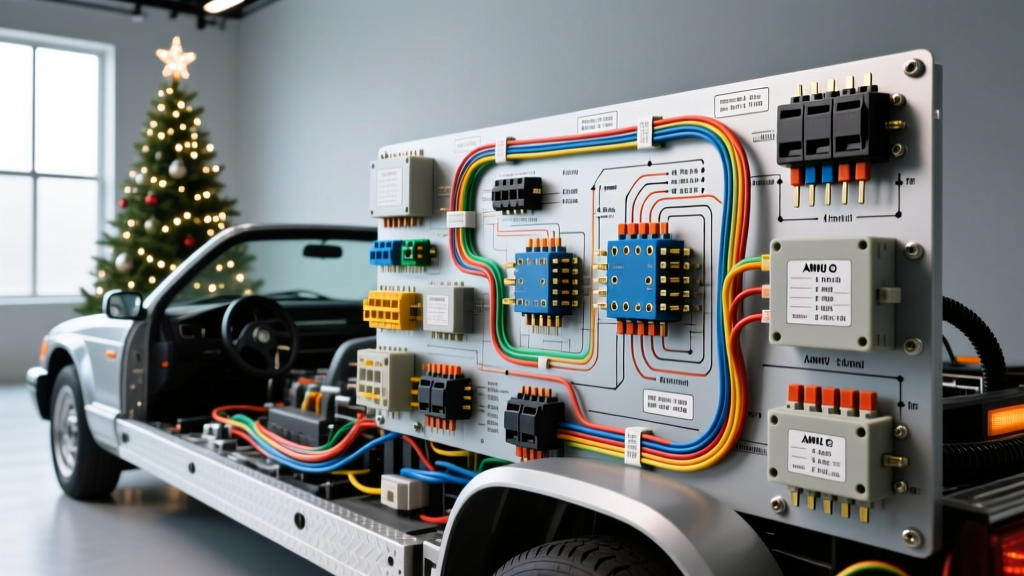
Introduction to Parade Float Electrical Systems
Powering a commercial holiday display on a moving parade float requires meticulous electrical planning. When towing a flatbed trailer carrying a massive, illuminated holiday display, standard trailer lighting is insufficient. You need a robust auxiliary power system capable of handling high continuous AC and DC loads. While OEM service manuals do not provide a specific wiring diagram for pre lit christmas tree applications, the principles of high-amperage automotive upfitting, inverter integration, and heavy-duty relay logic apply directly to this scenario.
This guide provides a comprehensive, practical installation walkthrough for integrating a 2000W Pure Sine Wave inverter and a Bosch-style relay harness into a modern tow vehicle (such as a 2015-2023 Ford F-150 or F-250) to safely power a trailer-mounted display. We will cover AWG wire sizing, SAE-compliant connector selection, and precise pinout configurations to ensure your parade rig operates without voltage drop or thermal failure.
Calculating the Electrical Load for Commercial Holiday Displays
Before cutting a single wire, you must calculate the total amperage draw of your display. A commercial-grade pre-lit artificial tree utilizing traditional incandescent mini-lights can easily draw 15 to 20 amps at 120V AC. Even with LED conversions, the initial inrush current of the transformers and motorized rotating bases requires significant overhead.
- Total Continuous Load: 15A at 120V AC (1800 Watts)
- Inverter Efficiency Factor: 85% (Standard for Pure Sine Wave)
- Required DC Input: 1800W / 12V DC / 0.85 = 176 Amps continuous
- Peak Inrush Surge: Up to 250 Amps for 2 seconds
Because the DC amperage on the 12V side is exceptionally high, treating this as a standard accessory circuit will result in melted insulation or a vehicle fire. We must treat the inverter feed as a primary battery cable run, adhering strictly to SAE J1128 Low Tension Primary Cable standards for thermal resistance.
Component Selection and AWG Wire Sizing
Selecting the correct American Wire Gauge (AWG) is critical to preventing voltage drop. A voltage drop of more than 3% on the 12V DC side will cause the inverter's low-voltage cutoff to trigger, shutting down your display mid-parade.
| Circuit Segment | Recommended AWG | Max Length (One Way) | Insulation Type |
|---|---|---|---|
| Battery to Inverter (Main Feed) | 1/0 AWG | 15 Feet | SGT / SAE J1128 (105°C) |
| Inverter Ground to Chassis | 1/0 AWG | 5 Feet | SGT / SAE J1128 (105°C) |
| Relay Pin 30 (12V+ Source) | 10 AWG | 10 Feet | GXL / Cross-linked |
| Relay Pin 87 (12V+ to Trailer) | 10 AWG | 25 Feet | GXL / Cross-linked |
| Upfitter Switch Trigger (Pin 86) | 18 AWG | 15 Feet | Standard PVC |
For the main 1/0 AWG inverter feed, you must use a 200-amp ANL fuse mounted within 18 inches of the battery positive terminal. For the trailer connection, utilize a heavy-duty 7-Way RV blade connector, specifically tapping into the Pin 4 (Auxiliary 12V+) and Pin 1 (Ground) circuits.
The Core Wiring Diagram for Pre Lit Christmas Tree Setups
To prevent the inverter from draining the vehicle's starter battery when the engine is off, we use a heavy-duty 5-pin Bosch-style relay (rated for 40A/60A) controlled by the vehicle's Upfitter switches or an ignition-sense module. Below is the logical flow of the relay harness:
Bosch 5-Pin Relay Pinout Configuration
- Pin 30 (Red 10 AWG): Constant 12V+ from the auxiliary fuse block (fused at 30A).
- Pin 87 (Blue 10 AWG): Switched 12V+ output running to the trailer's 7-way Pin 4 (Auxiliary Power). This triggers the inverter's remote on/off terminal or powers a secondary 12V lighting bus.
- Pin 86 (Green 18 AWG): Trigger wire connected to the Ford Upfitter Switch #1 (Blunt cut wire under the dash, typically Violet/White stripe on 2015+ F-Series).
- Pin 85 (Black 12 AWG): Chassis ground. Must be secured to bare, unpainted metal using a star washer and treated with dielectric grease.
- Pin 87a (Not Used): Tape off and heat-shrink. This is the normally-closed contact, which we do not need for this application.
For detailed vehicle-specific upfitter pinouts and chassis grounding locations, always consult the Ford Truck Body Builder Advisory Service documentation for your specific model year.
Step-by-Step Installation Guide
Step 1: Main Inverter Power and Ground Routing
Disconnect the negative battery terminal. Route the 1/0 AWG red SGT cable from the battery positive terminal, through the firewall grommet (using a silicone firewall seal), to the inverter's location in the cab or bed-mounted toolbox. Install the 200A ANL fuse holder immediately after the battery lug. Crimp all 1/0 AWG terminals using a 12-ton hydraulic crimper with hexagonal dies, and seal the connections with 3M adhesive-lined dual-wall heat shrink.
Step 2: Installing the 7-Way Trailer Connector Auxiliary Feed
Many factory 7-way connectors only provide 30 amps to the auxiliary pin. If your display requires a dedicated 12V trigger line for a remote inverter, run a new 10 AWG GXL wire from the engine bay auxiliary fuse box directly to the back of the 7-way plug. Use a standard etrailer 7-way wiring harness adapter if splicing into the OEM plug is not feasible. Pin 4 is your 12V+ auxiliary, and Pin 1 is your white ground wire.
Step 3: Integrating the Relay and Upfitter Trigger
Mount the 40A Bosch relay in a weatherproof Deutsch DT connector housing under the hood. Splice the Pin 86 trigger wire into the Upfitter Switch #1 blunt-cut wire located under the driver's side dash. When the driver toggles Switch #1 on the overhead console, it sends a 12V+ signal to Pin 86, energizing the coil and closing the circuit between Pin 30 and Pin 87, sending power to the trailer.
Troubleshooting Voltage Drop and Grounding Issues
Even with a perfect wiring diagram for pre lit christmas tree parade setups, environmental factors and poor workmanship can cause failures. Use a digital multimeter (DMM) to diagnose these common issues:
Symptom: Inverter Shuts Down Under Load (Low Voltage Alarm)
- Cause: Excessive voltage drop on the 12V DC side due to undersized wire or poor crimps.
- Fix: Perform a voltage drop test. Place the DMM positive probe on the battery positive post and the negative probe on the inverter positive terminal while the tree is illuminated. A reading above 0.2V indicates high resistance. Re-crimp the 1/0 AWG lugs and ensure the hydraulic crimp die was properly matched.
Symptom: Trailer Auxiliary Pin 4 Has No Power
- Cause: Blown inline fuse on the relay Pin 30 feed, or a corroded ground on Pin 85.
- Fix: Check the 30A ATC fuse in the engine bay. Next, test continuity between the relay socket's Pin 85 terminal and the negative battery terminal. If resistance is above 5 ohms, scrape the chassis ground point down to bare steel and re-torque the ground bolt to 15 lb-ft.
Symptom: Flickering Lights on the Tree Display
- Cause: The inverter is a Modified Sine Wave (MSW) rather than a Pure Sine Wave (PSW), or the 120V AC extension cords running from the truck bed to the trailer are undersized (e.g., using 16 AWG household cords for a 15A load).
- Fix: Upgrade to a Pure Sine Wave inverter to protect the tree's LED transformers. Replace all 120V AC extension cords with 12 AWG or 10 AWG SJTW outdoor-rated cables to minimize AC voltage drop across the trailer tongue.
Final Safety Inspections
Before taking your parade float onto the route, conduct a full-load burn-in test. Turn on the entire pre-lit tree display and let it run for 45 minutes with the truck idling. Use an infrared thermal camera to scan the ANL fuse, the 1/0 AWG cable runs, the relay terminals, and the 7-way trailer plug. Any component exceeding 140°F (60°C) indicates a high-resistance connection that must be rebuilt. By adhering to SAE standards and utilizing heavy-duty automotive wiring practices, your holiday display will remain brilliantly lit from the staging area to the final parade route.