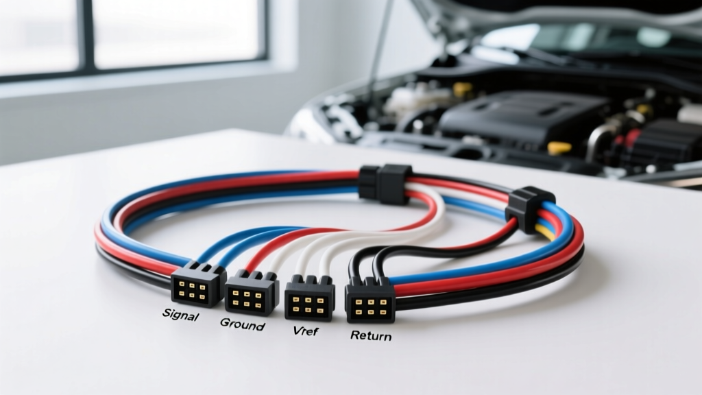
The Anatomy of a Melted Harness Nest
Engine bays of modern performance and daily-driver vehicles alike are hostile environments characterized by extreme thermal cycling, high-frequency vibration, and corrosive chemical exposure. Over time, factory corrugated looms become brittle, high-temperature harness tape unravels, and plastic zip-ties degrade. When protective heat shields fail or are removed during aftermarket exhaust modifications, the primary engine harness can drop directly onto exhaust manifolds or cylinder heads. In the automotive electrical diagnostic world, this degraded, shorted, and melted mass of copper is colloquially termed a 'rat's nest.' When technicians are forced to excavate a melted rat's nest wiring diagram 4 wire configurations are the most frequently damaged due to their mandatory placement upstream of the catalytic converter.
Unlike older 1-wire or 3-wire sensors, the modern 4-wire Heated Oxygen Sensor (HO2S) requires both a dedicated high-current heater circuit and a highly sensitive millivolt signal circuit. When these wires melt together inside a harness nest, the resulting short-to-ground or short-to-voltage can instantly destroy the Powertrain Control Module (PCM) internal driver transistors. This advanced technical deep dive will dissect the 4-wire HO2S circuit architecture, provide OEM pinout references, and outline the exact high-temperature repair protocols required to fix a melted harness nest without causing a comeback.
Zirconia Cell Theory & 4-Wire Circuit Breakdown
To properly diagnose a damaged 4-wire harness, one must understand the electrochemical principles governing the sensor. The 4-wire HO2S utilizes a zirconium dioxide (ZrO2) ceramic element coated with porous platinum electrodes. This setup acts as a Nernst cell, generating a voltage potential based on the difference in oxygen concentration between the exhaust gas and the ambient reference air trapped inside the sensor thimble.
- Signal Circuit (Wire 3): Generates a voltage ranging from 0.1V (lean mixture, high oxygen) to 0.9V (rich mixture, low oxygen). Stoichiometric equilibrium (14.7:1 air/fuel ratio) rests at approximately 0.45V.
- Signal Reference/Low (Wire 4): Provides a dedicated, isolated analog ground path back to the PCM's analog-to-digital converter (ADC). This prevents voltage drop from engine block grounds from skewing the millivolt signal.
- Heater Power (Wire 1): Supplies fused 12V+ ignition or battery voltage to the internal resistive heating element.
- Heater Ground (Wire 2): Controlled by the PCM via a Pulse Width Modulated (PWM) low-side driver. The PCM monitors the internal resistance of the heater element to maintain the zirconia cell at the optimal operating temperature of 600°C to 850°C, ensuring rapid light-off during cold starts to meet emissions standards.
OEM Pinout & Wire Color Specification Table
While wire colors can vary by manufacturer and model year, the functional architecture remains consistent. Below is a reference table for common GM LS and Ford Modular/Coyote V8 applications, which are notorious for harness nest issues near the rear of the cylinder heads.
| Pin | Function | Typical GM LS Color | Typical Ford Coyote Color | AWG | Circuit Type |
|---|---|---|---|---|---|
| A | Heater 12V+ Power | Pink/Black | White/Red | 18-20 | High Current (Fused) |
| B | Heater Ground (PWM) | Black/White | White/Blue | 18-20 | PCM Low-Side Driver |
| C | O2 Signal High | Purple | Grey/Red | 20 | High-Z Analog Signal |
| D | O2 Signal Low (Ref) | Tan | Grey/White | 20 | Isolated Analog Ground |
Note: Always verify pinouts with a factory service manual (FSM) specific to your VIN, as connector keyways (Bosch EV1 vs. Denso rectangular) dictate physical pin orientation.
Wire Gauge, Insulation, and High-Temp Routing Standards
The most critical mistake made when repairing a melted harness nest is the use of standard PVC or TXL insulated wire. Standard TXL (Cross-linked polyethylene) wire is rated to approximately 125°C (257°F). Exhaust manifolds routinely exceed 400°C (752°F) under load. If TXL wire is used to repair a 4-wire O2 pigtail, the insulation will melt, shrink, and recreate the exact same short-circuit nest within 500 miles.
According to the SAE J1128 Standard for low-tension primary cable, high-temperature engine bay applications require specialized insulation. For the sensor-side pigtail, you must use 20 AWG PTFE (Teflon) or MIL-W-16878 Type E wire, which is rated for continuous operation at 200°C and can withstand momentary spikes up to 250°C. For the chassis-side harness repair, 18 AWG GXL or SXL wire is acceptable, provided it is routed through fiberglass sleeving and secured away from the exhaust manifold using stainless steel cushion clamps rather than nylon zip-ties.
Diagnostic Decision Tree: Tracing a Melted Harness Nest
When a harness nest causes a short, the PCM will typically log specific Diagnostic Trouble Codes (DTCs). Use this decision tree to isolate the fault before cutting into the harness.
Scenario 1: Heater Circuit DTCs (P0030, P0031, P0032)
- Check Resistance: Disconnect the sensor and PCM. Measure resistance across the heater pins (A and B) at the sensor. A healthy zirconia heater typically reads between 2.0 and 8.0 ohms at 20°C. An open circuit (OL) indicates a melted internal trace.
- Check for Short-to-Ground: If DTC P0031 (Heater Control Circuit Low) is present, test continuity from Pin B (Heater Ground) to the engine block. If continuity exists with the PCM disconnected, the harness nest has melted the PWM wire into a ground plane, or the PCM driver is internally shorted.
- Oscilloscope Verification: Backprobe Pin B at the sensor connector with the engine running. A healthy PCM will command a 100% duty cycle (solid ground) on cold startup, rapidly transitioning to a 20-40% PWM duty cycle as the sensor reaches 600°C. A flat 0V or 12V line indicates a severed wire in the nest.
Scenario 2: Signal Circuit DTCs (P0130, P0131, P0132)
- Bias Voltage Check: With the sensor disconnected and key-on-engine-off (KOEO), measure voltage between the harness-side Signal High and Signal Low wires. The PCM should provide a bias voltage of exactly 0.45V. If you read 0V or 12V, the signal wires are shorted together or to adjacent circuits inside the melted loom.
- Parasitic Backfeeding: A common symptom of a harness nest is 'cross-talk,' where the 12V heater power wire melts into the millivolt signal wire. This will force the PCM to read a permanent 12V (or 5V, depending on the ADC clamp diode), resulting in a P0132 (High Voltage) code and forcing the engine into a severe open-loop limp mode.
Proper Repair Protocol for 4-Wire Sensor Circuits
Once the damaged section of the nest is excised, the repair must meet OEM environmental sealing standards. The Bosch Mobility Solutions engineering guidelines emphasize that oxygen sensor connectors are highly susceptible to micro-fretting corrosion and thermal shock.
- Terminal Crimping: Never use standard open-barrel crimps for the sensor-side pigtail. Use OEM-style Deutsch DT or Bosch EV1 sealed connectors with the correct wire seal inserts. The crimp must be performed with a ratcheting terminal tool to ensure gas-tight compression.
- Splicing Method: Do not use twist-caps or standard electrical tape. Use dual-wall, adhesive-lined heat shrink tubing with an integrated solder ring (e.g., Raychem RT555). The inner thermoplastic adhesive must melt and flow into the wire strands to prevent capillary action from drawing moisture into the PCM.
- Thermal Protection: Wrap the repaired 4-wire bundle in high-silica fiberglass sleeving (rated to 1000°F). Secure the harness to the engine block using factory-style aluminum stand-off brackets. Never zip-tie an O2 sensor harness directly to an exhaust pipe or cylinder head runner.
Conclusion & Authoritative References
Repairing a 4-wire O2 sensor harness nest requires more than just restoring continuity; it demands an understanding of high-impedance analog signals, PWM thermal management, and extreme-temperature material science. By utilizing PTFE-insulated wire, sealed OEM connectors, and rigorous oscilloscope diagnostics, technicians can permanently resolve these complex electrical faults. For further reading on automotive wire insulation standards and sensor theory, consult the International Automotive Technicians Network (IATN) archives and SAE technical papers on Nernst cell degradation.