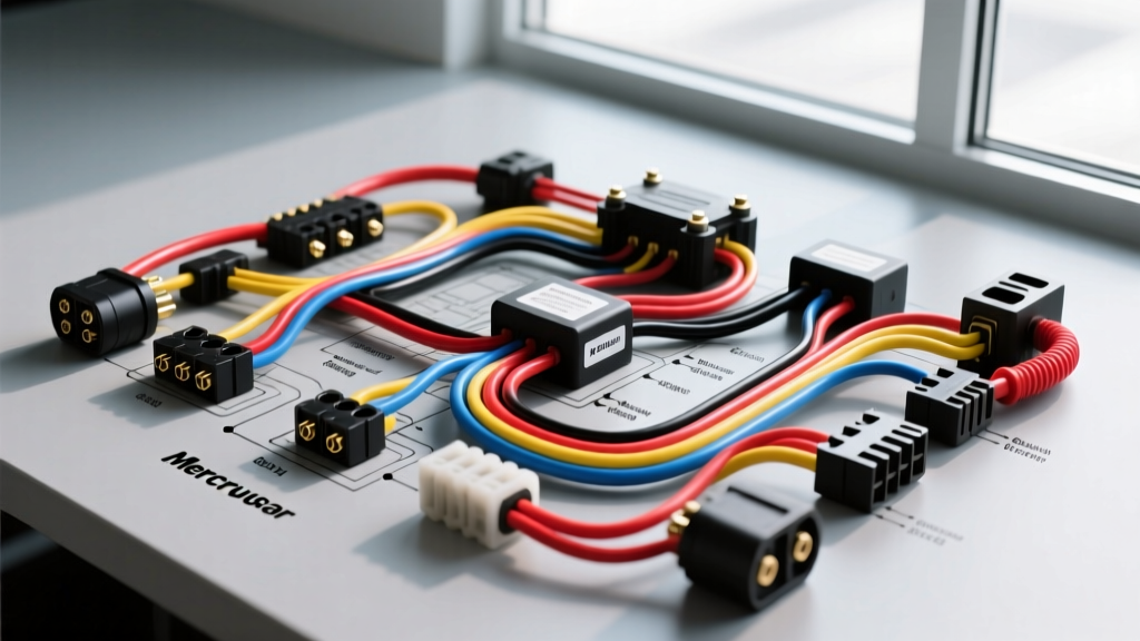
Introduction to the MerCruiser 3.0L Electrical System
The MerCruiser 3.0L (GM 181 CID inline-4) is one of the most reliable and widely deployed marine sterndrive engines in the world. While the base engine block shares its lineage with automotive applications, the marine electrical system requires a completely different approach to wiring, corrosion resistance, and ignition protection. Understanding the complete wiring diagram Mercruiser 3.0 configuration is critical for diagnosing no-start conditions, upgrading alternators, or repinning degraded bulkhead connectors. This technical specification reference details the OEM wire color codes, AWG sizing, cannon plug pinouts, and safety interlock circuits specific to the MerCruiser 3.0L engine family.
USCG and ABYC Marine Wiring Standards
Before modifying or repairing any MerCruiser 3.0 harness, technicians must recognize that marine wiring differs fundamentally from automotive wiring. According to ABYC Marine Electrical Standards (specifically E-11 for AC/DC electrical systems), all primary conductors must be stranded, tinned copper to resist 'black wire syndrome' (galvanic corrosion inside the insulation). Furthermore, all ignition components, including the distributor, EST modules, and alternators, must meet SAE J1171 Ignition Protection standards to prevent sparking in the bilge where combustible fuel vapors may accumulate. Never substitute standard automotive wire or non-ignition-protected sensors when servicing the 3.0L harness.
Main Harness and Cannon Plug Pinout Configuration
The MerCruiser 3.0L engine harness interfaces with the vessel's dashboard and battery via a marine-grade, weather-sealed bulkhead connector, commonly referred to as the 'cannon plug.' Depending on the model year and whether the engine is equipped with Thunderbolt IV or V ignition, this is typically a 14-pin or 16-pin circular connector. Below is the standard OEM pinout reference for the 14-pin engine-to-dash harness.
| Pin | Wire Color | AWG | Circuit Function |
|---|---|---|---|
| A | Red | 10 | Constant 12V+ Battery Feed (Fused) |
| B | Purple | 14 | Switched 12V+ from Ignition Switch (Run) |
| C | Yellow | 12 | Starter Solenoid Crank Signal (Start) |
| D | Dark Blue | 16 | Choke Solenoid / Alternator Field Excite |
| E | Gray | 18 | Tachometer Signal (Coil Negative) |
| F | Tan | 18 | Water Temperature Sender Signal |
| G | Pink | 18 | Fuel Tank Sender Signal |
| H | Black | 10 | Main Harness Ground Return |
| I | Light Blue | 16 | Oil Pressure Switch / Alarm Module |
| J | Purple/White | 14 | Fuel Pump Relay Trigger (Post-Start) |
Ignition and Starting Circuit Specifications
The starting circuit on the MerCruiser 3.0L utilizes a heavy-duty marine slave solenoid mounted near the starter motor. The main battery cable running from the battery to the starter solenoid should be a minimum of 2 AWG or 4 AWG tinned marine cable, depending on the cable run length (runs exceeding 10 feet require 2 AWG to prevent voltage drop). The ignition switch sends a 12V+ signal via a 12 AWG Yellow wire to the 'S' terminal on the slave solenoid. When engaged, the slave solenoid bridges the high-amperage battery feed to the starter motor while simultaneously providing 12V+ to the ignition coil's positive terminal to compensate for voltage drop during cranking.
Electronic Spark Timing (EST) and Thunderbolt Modules
Later model 3.0L engines utilize the MerCruiser Thunderbolt IV or Thunderbolt V Electronic Spark Timing (EST) systems. The distributor contains a magnetic pickup assembly rather than traditional mechanical points and condenser. The magnetic pickup sends an AC voltage signal to the Thunderbolt module, which processes the signal and triggers the ignition coil.
- White/Orange Wire: Connects to the negative terminal of the ignition coil and the tachometer signal output.
- Black/White Wire: Provides the primary ground path for the module; must be secured to a clean, unpainted metal surface on the intake manifold or cylinder head.
- Red/White Wire: Switched 12V+ ignition feed.
Fuel Pump Relay and Oil Pressure Safety Interlock
One of the most misunderstood circuits in the Mercruiser 3.0 wiring diagram is the fuel pump safety interlock. To prevent the electric fuel pump from running if the ignition key is left in the 'ON' position while the engine is stalled (which could flood the bilge with raw fuel in the event of a ruptured line), MerCruiser employs an oil pressure switch parallel to the fuel pump relay. During the 'CRANK' position, the ignition switch directly powers the fuel pump relay. Once the key is released to the 'RUN' position, the relay drops out. However, as the engine builds oil pressure (typically above 4 PSI), the 3-terminal oil pressure switch closes, providing a secondary 12V+ path from the Purple ignition wire to the fuel pump via the Purple/White wire. If the engine loses oil pressure while running, the switch opens, cutting power to the fuel pump and safely shutting down the engine.
Charging System and Alternator Wiring
The MerCruiser 3.0L is typically equipped with a Delco 10SI or 12SI style marine alternator, rated between 55 and 65 amps. While automotive applications often use a 1-wire 'self-exciting' setup, marine applications frequently utilize a 3-wire configuration to ensure accurate voltage sensing at the battery bank, compensating for voltage drop across the main battery isolator switch.
- BAT Terminal: Direct connection to the battery positive or common busbar (8 AWG or 6 AWG).
- Terminal #1 (Excite): Connected to a dash-mounted charge indicator lamp or a switched 12V+ ignition source via a Dark Blue wire. This provides the initial field current to 'turn on' the alternator.
- Terminal #2 (Sense): Must be wired directly to the positive side of the battery bank or the main distribution bus to accurately read system voltage. If this wire is lost or broken, the alternator will default to maximum output, potentially boiling the marine battery.
Instrument Panel and Sender Wire Color Codes
Accurate gauge readings depend on matching the correct sender resistance to the gauge type (American vs. European standard). MerCruiser standard gauges utilize the following wire colors from the cannon plug to the dash:
| Gauge | Sender Wire Color | Sender Resistance Range | Ground Reference |
|---|---|---|---|
| Water Temp | Tan | 240 Ohms (Cold) to 33 Ohms (Hot) | Engine Block |
| Oil Pressure | Light Blue | 0 Ohms (0 PSI) to 160 Ohms (80 PSI) | Engine Block |
| Fuel Level | Pink | 240 Ohms (Empty) to 33 Ohms (Full) | Fuel Tank Sender |
| Tachometer | Gray | N/A (Pulse Signal) | Coil Negative |
Troubleshooting Common MerCruiser 3.0 Electrical Faults
When diagnosing electrical faults on the 3.0L, follow this systematic decision tree to isolate the failure point without replacing unnecessary components:
Symptom: Engine Will Not Crank (No Click, No Turnover)
- Check Main Circuit Breaker: Locate the 90-amp main fuse or manual reset circuit breaker on the starter solenoid. Use a multimeter to verify 12V+ on both sides of the breaker.
- Test Ignition Switch Output: Turn the key to 'START'. Probe the Yellow wire at the ignition switch and at the cannon plug. If voltage is present at the switch but not the plug, the vessel's intermediate harness is compromised.
- Verify Neutral Safety Switch: The MerCruiser sterndrive outdrive features a neutral safety switch interrupter. If the shift lever is not perfectly centered in neutral, the switch will break the Yellow crank circuit. Bypass the switch temporarily at the shift bracket to confirm diagnosis.
Symptom: Engine Cranks But Will Not Start (No Spark)
- Verify Coil Voltage: Check for 12V+ at the positive terminal of the ignition coil while the key is in the 'RUN' position. If missing, trace the Purple wire back through the emergency lanyard kill switch. The lanyard switch physically interrupts the Purple ignition feed.
- Test Coil Resistance: Disconnect the battery. Measure primary resistance between the coil's positive and negative terminals (should be 0.5 to 1.5 ohms). Measure secondary resistance from the positive terminal to the center high-tension tower (should be 8,000 to 12,000 ohms).
- Inspect EST Module Ground: The Thunderbolt module is highly sensitive to poor grounds. Remove the Black/White ground wire, sand the mating surface on the intake manifold to bare metal, and reinstall using a star washer. Torque to 120 in-lbs.
Authoritative References and Service Data
For complete, year-specific schematics and torque specifications, technicians should consult the official Mercury Marine Service Manuals corresponding to their engine serial number. Always adhere to ABYC E-11 guidelines when fabricating replacement harnesses, and ensure all crimp connections are sealed with marine-grade heat shrink containing internal polyamide adhesive to prevent moisture ingress.