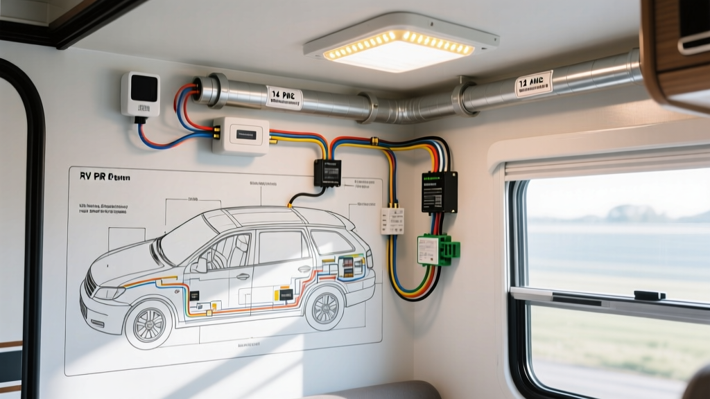
Automotive PIR Integration: Beyond Residential Schematics
Integrating a perimeter security and convenience lighting system on an RV, overland camper, or heavy-duty service truck requires more than simply adapting off-the-shelf residential components. When referencing a standard wiring diagram for motion detector light applications in residential settings, the transition to a 12V DC automotive platform requires a fundamental redesign of the switching mechanism, transient protection, and environmental sealing. Residential passive infrared (PIR) sensors rely on 120V AC zero-crossing circuits and TRIAC switches, which will instantly fail or cause a fire hazard when connected to a 12V DC vehicle battery. Automotive-grade PIR modules, however, utilize internal solid-state relays or open-collector transistor outputs designed to handle the harsh electrical environment of a vehicle, including load dump events and extreme thermal cycling.
This comprehensive wiring walkthrough details the exact schematic, wire gauge requirements, and connector pinouts required to install a dual-flood LED motion security system on an RV or truck chassis. By adhering to SAE J1128 standards for low-tension primary automotive cable, this system ensures long-term reliability, minimal voltage drop, and complete resistance to the elements.
System Architecture and Component Specifications
Before cutting or stripping any wire, it is critical to match the component specifications to the electrical load. The system outlined below powers two 40W exterior LED flood lights (total draw: 80W / ~6.6A at 12V) using an automotive-rated 12V DC PIR sensor and a heavy-duty Bosch-style relay.
| Component | Specification / Rating | Wire Gauge (AWG) | Connector Type |
|---|---|---|---|
| Main Power Feed | 15A ATO Blade Fuse | 14 AWG (XLPE Insulation) | Ring Terminal (5/16") |
| PIR Motion Sensor | 10-30V DC, IP67, Open Collector Out | 16 AWG (Control Circuit) | 3-Pin Delphi Weather-Pack |
| Switching Relay | 12V DC SPST NO, 30A/40A Bosch ISO | 14 AWG (Load), 16 AWG (Coil) | Standard ISO Relay Socket |
| LED Flood Lights (x2) | 40W Each (6.6A Total Draw) | 14 AWG (Load Circuit) | 2-Pin Delphi Weather-Pack |
| Transient Protection | 1N4004 Flyback Diode | N/A (Soldered at Relay Socket) | N/A |
The Importance of Transient Voltage Protection
Vehicle alternators can produce severe voltage spikes—known as load dump—when a battery connection is suddenly interrupted while charging. According to ISO 7637-2 Pulse 5 testing, these spikes can exceed 40V for hundreds of milliseconds, easily destroying the delicate logic board inside a PIR sensor. Furthermore, when the relay coil de-energizes, it creates an inductive kickback (flyback voltage) that can travel backward into the PIR sensor's output transistor, causing premature failure. Installing a 1N4004 flyback diode across the relay coil pins (85 and 86) is a non-negotiable step in this wiring diagram to clamp this reverse voltage spike.
Complete Wiring Diagram Walkthrough
The following step-by-step node breakdown translates the visual schematic into actionable routing instructions. Always disconnect the negative battery terminal before beginning any automotive electrical work.
Node 1: Power Distribution and Fusing
- Battery to Fuse: Route a 14 AWG Red wire from the positive battery terminal (or a dedicated auxiliary busbar) to an inline 15A ATO waterproof fuse holder. Keep this unfused segment as short as physically possible (under 18 inches) to prevent catastrophic short circuits.
- Fuse to Relay (Pin 87): Run 14 AWG Red from the output side of the fuse holder to Pin 87 (Normally Open contact) on the Bosch relay socket.
- Fuse to PIR Sensor (Pin 1): Splice into the same fused 14 AWG line using a heat-shrink butt connector, stepping down to a 16 AWG Red wire that routes to Pin 1 (VCC / +12V) on the PIR sensor's 3-pin Weather-Pack connector.
Node 2: PIR Sensor Pinout and Grounding
Automotive PIR sensors typically utilize a standardized 3-pin configuration. Verify your specific manufacturer's pinout, but the industry standard for RVIA-compliant security modules is as follows:
- Pin 1 (Red Wire): +12V Constant Power (from Node 1).
- Pin 2 (Black Wire): Chassis Ground. Route a 16 AWG Black wire to a clean, bare-metal grounding point on the vehicle chassis. Use a self-tapping grounding screw with a star washer to bite through the paint and ensure a zero-ohm connection.
- Pin 3 (Blue Wire): Trigger Output. This open-collector output sinks to ground when motion is detected. Route a 16 AWG Blue wire from Pin 3 to Relay Pin 85 (Coil Ground).
Node 3: Relay Coil and Flyback Diode Integration
The relay acts as the heavy-duty bridge between the low-current PIR sensor and the high-current LED flood lights.
- Relay Pin 86 (Coil Power): Connect a 16 AWG Red wire from a switched or constant 12V source to Pin 86. (Use constant 12V if you want the motion lights active 24/7; use a switched 12V source if you only want them active when the ignition or an interior toggle switch is engaged).
- Relay Pin 85 (Coil Ground): Connect the 16 AWG Blue trigger wire from the PIR Sensor Pin 3.
- Diode Placement: Solder a 1N4004 diode directly across the female terminals of Pins 85 and 86 on the relay socket. The silver stripe (cathode) of the diode must face Pin 86 (+12V). This orientation allows normal current flow to energize the coil but catches the reverse inductive spike when the PIR sensor cuts the ground.
Node 4: Load Circuit to LED Floods
- Relay Pin 30 (Common / Output): Run a 14 AWG Red wire from Pin 30 to the positive inputs of the exterior LED flood lights. If wiring two lights, use a sealed Y-splitter or solder-seal heat shrink connectors to branch the 14 AWG feed into two 16 AWG drops for the individual light fixtures.
- Light Grounds: Ground the LED fixtures locally to the chassis using 14 AWG Black wire and star washers, or route the ground back to the main auxiliary ground busbar.
Delphi Weather-Pack Connector Pinouts and Crimping
Exterior automotive connections must be sealed against moisture and road salt. The Delphi Weather-Pack series remains the gold standard for exterior RV and truck lighting. When assembling the 3-pin connector for the PIR sensor:
- Strip exactly 5/32" of insulation from the 16 AWG wire.
- Use a dedicated Weather-Pack crimp tool (ratcheting die) to crimp the terminal to the wire core, and the insulation grip to the jacket.
- Slide the neoprene weather seal onto the wire before crimping the terminal.
- Insert the crimped terminal into the nylon connector housing until you hear an audible click, confirming the terminal tang has engaged the housing lock.
- Apply dielectric grease to the mating connector pins to prevent galvanic corrosion and moisture ingress.
Real-World Failure Modes and Multimeter Diagnostics
Even with a perfect wiring diagram for motion detector light installations, environmental factors and improper installation can lead to system faults. Use this diagnostic decision tree to troubleshoot common issues.
Symptom: Lights Remain On Continuously (Will Not Shut Off)
- Cause 1: Welded Relay Contacts. If the LED lights drew a massive inrush current (common with cheap, unregulated LED drivers), the internal contacts of the Bosch relay may have welded together in the closed position. Fix: Replace the relay and verify LED inrush current does not exceed 20A.
- Cause 2: PIR Sensor Output Transistor Short. If the flyback diode was omitted or installed backward, the inductive spike from the relay coil destroyed the PIR's internal transistor, causing it to short to ground permanently. Fix: Replace PIR sensor and install diode correctly.
Symptom: Lights Flicker or Trigger Falsely
- Cause 1: Thermal Interference. PIR sensors detect changes in infrared heat. If mounted too close to the vehicle's exhaust manifold, a hot radiator overflow, or directly above an exterior LED light that radiates heat backward through the mounting surface, the sensor will false-trigger. Fix: Relocate sensor away from heat sources and use the included opaque thermal-shield tape on the bottom of the Fresnel lens.
- Cause 2: Voltage Drop on Ground Circuit. A poor chassis ground on the PIR sensor or the LED lights can cause the sensor's internal logic board to reset erratically. Fix: Perform a voltage drop test across the ground circuit with the lights active. A reading above 0.1V indicates a corroded or loose ground connection.
Symptom: Lights Do Not Trigger at Night
- Cause 1: Integrated Photocell Misalignment. Many automotive PIR sensors feature a built-in CDS photocell to prevent daytime triggering. If the sensor is mounted under an awning or in a recessed bumper where it cannot detect ambient sky light, it may "think" it is always night, or conversely, if exposed to a nearby security lamp, it may think it is always day. Fix: Ensure the photocell window has a clear view of the ambient sky, or bypass the photocell circuit internally if 24/7 operation is desired.
Final Verification and System Testing
Once all connections are made, sealed, and secured with adhesive-lined cable ties away from moving suspension components and exhaust routing, reconnect the battery. Use a multimeter to verify 12.6V at the PIR sensor's VCC pin. Walk through the sensor's detection zone (typically a 120-degree cone extending up to 30 feet). The relay should audibly click, and the LED floods should illuminate instantly. Allow the timer to expire (usually adjustable via a potentiometer on the PIR module from 10 seconds to 5 minutes) and verify the lights shut off cleanly without flickering. Proper execution of this automotive wiring diagram guarantees a robust, weatherproof security lighting system capable of surviving the harshest overland and RV environments.