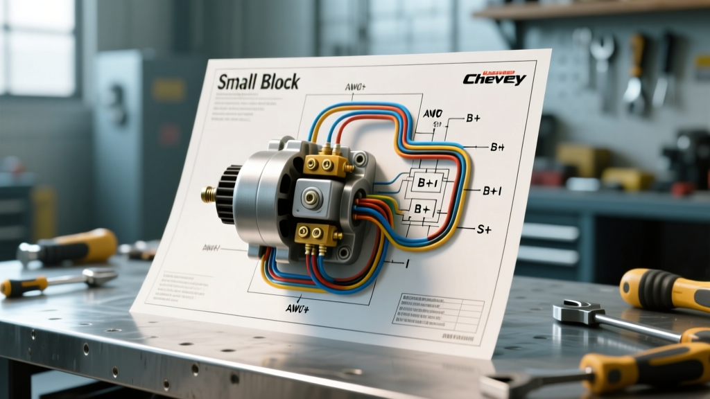
Introduction to Small Block Chevy Starter Circuits
Wiring the starter on a Small Block Chevy (SBC) is a fundamental rite of passage for any hot rod builder, restorer, or DIY mechanic. Whether you are working on a classic 1969 Camaro with a 350ci V8 or a 1985 C10 truck, the foundational electrical principles remain identical. The traditional Gen I and Gen II Small Block Chevy engines typically utilize either the classic Delco Remy 10MT direct-drive starter or the later, lighter PG260 permanent magnet gear-reduction starter. While the physical mounting and flexplate tooth engagement differ, the small block Chevy starter wiring diagram and solenoid terminal logic are universally consistent across these platforms.
For beginners, the starter circuit can seem intimidating due to the high amperage involved and the potential for catastrophic electrical fires if sized incorrectly. This guide breaks down the OEM-style wiring schematics, required AWG (American Wire Gauge) specifications, and modern relay upgrades to ensure your SBC cranks reliably every time, even when the engine is heat-soaked from a long drive.
Core Components of the Starter Wiring Diagram
A complete and safe SBC starter circuit consists of two distinct sub-circuits: the high-amperage cranking feed and the low-amperage control signal. Understanding the separation of these two circuits is the key to mastering automotive starter wiring.
1. The Main Battery Feed (High Amperage)
The main battery cable is responsible for delivering the massive surge of current required to turn the starter motor—often exceeding 250 amps under heavy load. Because of this extreme current draw, wire gauge selection is critical. According to SAE J1128 standards for low-tension primary cables, you must use a minimum of 2 AWG stranded copper wire for standard SBC builds. If your battery is relocated to the trunk, or if you are running a high-torque starter for a high-compression engine, you must upgrade to 1/0 AWG (one-aught) to minimize voltage drop over the extended distance.
Always use heavy-duty, adhesive-lined heat shrink terminals and a proper hex-crimp tool or hydraulic crimper. Soldering large-gauge battery cables is discouraged in high-vibration automotive environments, as the solder can wick into the wire strands, creating a brittle point that will eventually snap.
2. The Ignition Switch Feed (Low Amperage)
The control circuit triggers the starter solenoid. When you turn the key to the 'Start' position, the ignition switch sends a 12-volt signal to the 'S' terminal on the starter solenoid. This low-amperage signal (typically 10 to 15 amps) energizes the solenoid's internal electromagnetic coil. The coil pulls the heavy copper contact disc inward, bridging the main battery terminal to the starter motor, while simultaneously engaging the bendix drive gear into the flexplate.
For the control wire, 10 AWG or 12 AWG stranded copper is the OEM standard. In classic GM vehicles, this wire is almost universally color-coded Purple. This circuit must also be routed through a Neutral Safety Switch (NSS) on automatic transmissions or a clutch interlock switch on manual transmissions to prevent the vehicle from starting in gear.
Standard Delco Remy Solenoid Terminal Pinout
The Delco Remy solenoid mounted to the top of the SBC starter features three primary terminals. Misidentifying these is the most common beginner mistake. Below is the definitive pinout reference for the standard SBC starter solenoid:
| Terminal ID | Function | Recommended AWG | GM Standard Wire Color |
|---|---|---|---|
| B (BAT) | Main Battery Power Input (Constant 12V) | 1/0 AWG or 2 AWG | Red |
| S (Start) | Ignition Switch Crank Signal | 10 AWG or 12 AWG | Purple |
| I (Ignition) | Ballast Resistor Bypass (Points Ignition Only) | 14 AWG or 16 AWG | Pink or Yellow |
| Case | Starter Motor Ground Path | N/A (Engine Block) | Bare Copper Strap |
Note: The 'B' terminal uses a 3/8'-16 or 5/16'-18 threaded stud. Always torque the securing nut to 9-11 lb-ft. Over-tightening can crack the Bakelite solenoid cap, leading to moisture intrusion and internal short circuits.
The HEI Conversion and the 'I' Terminal
Beginners wiring an SBC often ask, 'What do I do with the 'I' terminal?' The answer depends entirely on your ignition system.
If your SBC uses a traditional points-style distributor, the ignition coil relies on a ballast resistor wire (usually a cloth-covered resistance wire) to drop the voltage to roughly 7-9 volts during normal running, preserving the points. However, during cranking, the engine needs a hotter spark. The 'I' terminal on the starter solenoid provides a temporary 12V bypass directly to the coil's positive terminal while the key is held in the 'Start' position. Once you release the key to the 'Run' position, the 'I' terminal loses power, and the coil reverts to the resistor wire.
If you have upgraded your SBC to a GM HEI (High Energy Ignition) distributor or an aftermarket CDI box (like an MSD 6AL), the HEI module requires a full, switched 12V source at all times. In this scenario, the 'I' terminal on the starter solenoid is left completely empty. You will instead run a dedicated 12 AWG wire from a switched 12V ignition fuse directly to the HEI cap's BAT terminal. Leaving the 'I' terminal empty on an HEI setup prevents dangerous voltage backfeed that can fry the HEI module.
Upgrading with a Starter Relay (Solving Heat Soak)
A common issue with Small Block Chevys, especially those equipped with tubular exhaust headers, is 'heat soak.' The starter solenoid sits mere inches from the primary exhaust tubes. As the solenoid heats up, its internal electrical resistance increases dramatically. When you turn the key to restart a hot engine, the ignition switch's 12V signal suffers from severe voltage drop across the long run of the Purple wire, failing to generate enough electromagnetic force to pull the solenoid contacts closed. You hear a single 'click,' but no crank.
The ultimate fix, highly recommended by experts at Painless Performance Products, is installing a heavy-duty starter relay. You can use a standard Bosch-style 40A relay mounted in the engine bay, or the classic 'Ford Fender Solenoid' trick.
Wiring the Engine Bay Relay:
- Relay Pin 30 (Power In): Run a short, heavy-gauge (4 AWG) jumper wire from the starter's 'B' terminal to Pin 30 on the relay.
- Relay Pin 87 (Power Out): Run a 10 AWG wire from Pin 87 directly to the starter's 'S' terminal.
- Relay Pin 86 (Coil Ground): Ground this pin securely to the engine block or cylinder head.
- Relay Pin 85 (Coil Trigger): Connect your original Purple wire (coming from the ignition switch and neutral safety switch) to this pin.
Now, the ignition switch only needs to power the tiny relay coil (drawing less than 1 amp), while the relay handles the heavy amperage required to trigger the starter solenoid, completely eliminating heat-soak voltage drop.
Grounding and Voltage Drop Testing
The starter circuit is only as good as its ground path. The SBC starter motor grounds through its mounting nose cone to the engine block. If your engine block is not properly grounded to the vehicle chassis and battery negative, the starter will attempt to ground through throttle cables, heater core hoses, or transmission shift linkages, instantly melting them.
You must install a minimum 2 AWG braided copper ground strap connecting the rear of the passenger side cylinder head (or the intake manifold bolt) directly to the vehicle's firewall or chassis. Furthermore, ensure the battery negative cable bolts directly to a clean, bare-metal point on the engine block, not just the chassis.
How to Perform a Voltage Drop Test:
Grab a digital multimeter and set it to DC Volts. Place the red probe on the battery positive post and the black probe on the starter 'B' terminal stud. Have an assistant crank the engine. The multimeter should read less than 0.20 volts. If it reads 0.50V or higher, your battery cable is undersized, corroded, or poorly crimped. Repeat the test on the ground side (Red probe on battery negative post, Black probe on starter case) to verify your engine ground straps.
Step-by-Step Wiring Sequence
Follow this sequence to ensure a safe, logical, and spark-free installation:
- Disconnect the Battery: Always remove the negative battery cable first and isolate it.
- Mount the Starter: Torque the starter mounting bolts to 35 lb-ft. Use the correct knurled starter bolts (they have a specific shoulder to align the starter nose with the block dowel pins).
- Install Ground Straps: Bolt the engine-to-chassis ground strap to clean, unpainted metal.
- Route the Main Cable: Route the 1/0 AWG red cable from the battery positive to the starter 'B' terminal, keeping it away from exhaust headers. Use high-temp wire loom where necessary.
- Connect the Control Wire: Attach the 10 AWG Purple wire to the 'S' terminal. Ensure the spade connector is tight; a loose spade will vibrate off during engine operation.
- Final Connections: Reconnect the battery negative cable last. Test the neutral safety switch before attempting to start the vehicle.
By adhering to these AWG specifications and terminal logic, your Small Block Chevy will feature a robust, reliable starter circuit capable of handling high-compression cranking loads for years to come.