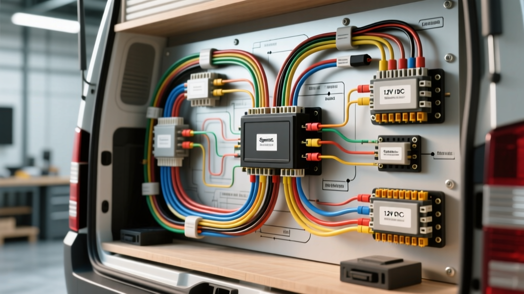
Architectural Overview: Vehicle Chassis vs. House Bank Integration
Integrating a high-fidelity home theater system into a motorized vehicle requires bridging two entirely distinct electrical ecosystems: the OEM chassis starting system and the aftermarket RV coach house battery bank. When troubleshooting a Mercedes-Benz Sprinter or Ford Transit conversion, technicians must reference a comprehensive home theater wiring diagram that accounts for 12V DC distribution, pure sine wave inversion, and electromagnetic interference (EMI) suppression. Unlike residential setups, RV home theaters are subjected to severe voltage fluctuations, alternator ripple, and chassis-induced ground loops. This guide provides a step-by-step troubleshooting flow to isolate faults in power delivery, signal routing, and amplifier triggering.
RV Home Theater DC Power Distribution & Wire Sizing Chart
Before probing logic boards or HDMI handshakes, verify that the foundational DC power delivery meets the American Boat & Yacht Council (ABYC) and RV Industry Association (RVIA) low voltage standards. Voltage drop over long wire runs in a 25-foot Sprinter chassis can cause AV receivers to enter protection mode during high-dynamic audio peaks.
| Component | Wire Gauge (AWG) | Wire Color Code | Max Run Length | Overcurrent Protection |
|---|---|---|---|---|
| 3000W Inverter DC Feed | 2/0 AWG Welding | Red (+) / Black (-) | 5 ft (1.5m) | 300A Class T Fuse |
| AV Receiver AC Input | 14 AWG (AC) | Standard IEC C13 | N/A (Inverter AC) | 15A AC Breaker |
| Amplifier 12V Direct Feed | 4 AWG Stranded | Red (+) / Black (-) | 12 ft (3.6m) | 60A ANL Fuse |
| Amp Remote Turn-On | 18 AWG | Blue w/ White Stripe | 20 ft (6m) | 5A Inline ATC |
| Speaker Wire (Main) | 12 AWG OFC | Clear/Copper (+/-) | 25 ft (7.6m) | N/A |
Step-by-Step Troubleshooting Flow
Use the following decision-tree methodology to isolate faults. Always begin with a digital multimeter (DMM) set to DC Volts and a known-good chassis ground reference.
Phase 1: Inverter & AC Power Faults
Symptom: AV Receiver and subwoofer amplifier show zero signs of life; no standby LED illumination.
- Step 1: Measure DC voltage at the inverter's main positive and negative bus bars.
- Result A (Below 11.5V): The LiFePO4 Battery Management System (BMS) has tripped, or the main Class T fuse is blown. Check house bank state-of-charge.
- Result B (12.8V - 13.4V): DC input is nominal. Proceed to Step 2.
- Step 2: Measure AC voltage at the inverter's output terminal block and the dedicated AV circuit breaker.
- Result A (0V AC): Inverter is in fault/shutdown mode. Check for overload or high-temperature cut-off. Reset via inverter control panel.
- Result B (115V - 120V AC): AC power is reaching the distribution panel. Proceed to Step 3.
- Step 3: Inspect the AV receiver's internal glass fuses and the IEC power cable continuity. Replace any blown 5A/250V fuses. If the unit remains dead, the internal switching power supply has failed due to transient voltage spikes.
Phase 2: Signal Loss, HDMI Routing & Ground Loops
Symptom: System powers on, but exhibits a high-pitched alternator whine that scales with engine RPM, or HDMI displays show 'No Signal' when the vehicle is in motion.
- Step 1 (Audio Whine): Disconnect the RCA interconnects from the amplifier.
- Whine Stops: The ground loop is originating from the source unit (AV Receiver). Ensure the receiver is grounded to the house battery bus bar, NOT the vehicle chassis. The Sprinter chassis carries heavy alternator ripple.
- Whine Persists: The amplifier's ground is compromised. Scrape away paint and rust at the amplifier's chassis ground point to ensure bare metal contact. Install a 12V DC ground loop isolator if necessary.
- Step 2 (HDMI Dropouts): Vehicle vibration causes micro-disconnects in standard residential HDMI cables.
- Fix: Replace standard friction-fit HDMI cables with locking HDMI connectors or route the signal through an HDBaseT Cat6 extender, which is far more resistant to EMI and physical vibration inside an RV wall cavity.
Phase 3: Amplifier Turn-On & Speaker Impedance
Symptom: AV Receiver operates normally, but the external subwoofer and channel amplifiers do not engage (Protect/Thermal LED is illuminated).
- Step 1: Probe the amplifier's 'REM' (Remote) terminal with a DMM while the ignition is ON.
- Result A (0V): The 12V trigger signal is not reaching the amp. Trace the Blue/White 18 AWG wire back to the Sprinter Upfitter Module (SAM) or the AV receiver's trigger out.
- Result B (12V+): Trigger signal is present. The amplifier is entering protection mode due to a speaker wiring fault.
- Step 2: Disconnect all speaker wires from the amplifier terminals. Power the amp on.
- Amp Powers On (Green LED): A short circuit exists in the speaker wiring or voice coil. Use the DMM in Ohms mode to measure impedance at the amplifier end. A reading below 1.5 Ohms on a 2-Ohm stable channel indicates a pinched wire shorting against the RV's metal chassis.
Sprinter Upfitter Module (SAM) Pinouts for AV Triggers
To prevent the home theater system from draining the house batteries when the vehicle is parked, the 12V remote turn-on wire must be tied to an ignition-sensed circuit. In modern Mercedes-Benz Sprinter vans, this is managed via the Signal Acquisition Module (SAM). Refer to the Mercedes-Benz Sprinter Upfitter Guidelines for the exact pin configurations of your specific model year.
| SAM Connector | Pin Number | Function | Wire Color (OEM) | Max Draw |
|---|---|---|---|---|
| X3/1 (Aux Relay 1) | Pin 4 | Ignition ON (Terminal 15) | Black/Yellow | 5A |
| X3/2 (Aux Relay 2) | Pin 2 | Run/Start Sense | Black/Red | 5A |
| X4/1 (Parametric) | Pin 8 | Ground Reference | Brown | N/A |
Expert Note: Never connect the amplifier remote wire directly to the SAM output. The SAM auxiliary circuits are typically limited to 5A or less, while multiple amplifiers and cooling fans can draw higher inrush currents. Use the SAM pin to trigger a 30A Bosch-style automotive relay, which then feeds the 12V trigger to the AV components from the main house distribution block.
Advanced EMI Suppression & Chassis Grounding
Automotive environments are electrically hostile. The Sprinter's high-output alternator and various CAN-bus modules generate significant electromagnetic interference. According to SAE J1113 Electromagnetic Compatibility Standards, sensitive audio and video equipment must be shielded from radiated and conducted emissions.
- Star Grounding Topology: Never daisy-chain the ground wires of your AV receiver, DSP (Digital Signal Processor), and amplifiers. Run individual, equal-length ground wires from each component to a single, centralized copper bus bar bonded directly to the house battery negative terminal.
- Ferrite Chokes: Install snap-on ferrite beads on all 12V trigger wires and unbalanced RCA interconnects near the source and destination ends to choke high-frequency RFI.
- Power/Signal Separation: When routing wires through the Sprinter's floor channels or wall cavities, maintain a minimum 6-inch separation between 120V AC/High-Current DC power cables and low-voltage audio/video signal cables. If they must cross, ensure they intersect at a strict 90-degree angle to minimize inductive coupling.
For further compliance and safety standards regarding low-voltage DC wiring in recreational vehicles, consult the RV Industry Association (RVIA) Low Voltage Standards. Proper adherence to these diagrams and troubleshooting flows ensures a reliable, noise-free cinematic experience, regardless of whether the Sprinter is idling at a campsite or cruising down the interstate.