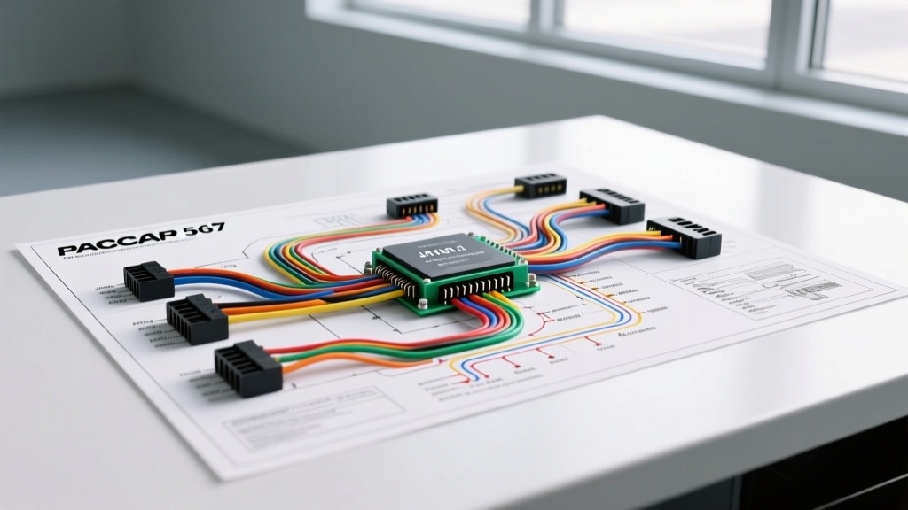
Decoding the Peterbilt 567 Electrical Architecture
Heavy-duty vocational trucks operate in some of the most punishing electrical environments on the road. The Peterbilt 567, engineered primarily for severe-duty applications like concrete mixers, heavy haulers, and dump trucks, relies on a complex hybrid electrical system. This system merges high-amperage hardwired circuits with highly sensitive multiplexed data networks. When sourcing and interpreting a Peterbilt 567 wiring diagram PDF, diesel technicians and upfitters must understand the distinction between the cab electronics controller (CEC) networks and the raw chassis power distribution.
Unlike light-duty vehicles, the 567 utilizes modular harness segments connected via sealed bulkhead pass-throughs and heavy-duty circular connectors. A complete schematic walkthrough requires analyzing the PACCAR MX-13 engine control module (ECM) pinouts, the SAE J1939 CAN bus backbone, and the dedicated power take-off (PTO) upfitter interfaces. This guide provides the critical wire color codes, AWG specifications, and connector cavity mappings necessary to accurately diagnose faults or engineer custom upfitter integrations.
Navigating the Peterbilt 567 Wiring Diagram PDF
Peterbilt schematic PDFs are structured differently than standard automotive wiring diagrams. They are divided into distinct logical blocks rather than physical routing maps. To effectively use the documentation, you must understand the nomenclature and legend conventions used by PACCAR and Peterbilt electrical engineers.
Circuit Identification and Connector Mapping
- Circuit IDs: Every wire is labeled with a unique alphanumeric circuit ID (e.g., CIR-450A). This ID remains constant throughout the entire harness, from the battery box to the CEC gateway.
- Connector Cavity Views: The PDF will display connector faces using a 'wire insertion view' (looking into the terminal end). Always verify pin numbering against the physical Deutsch or Amphenol connector shell, as heavy-duty connectors often use non-sequential keying.
- Splice and Ground Nodes: Ground nodes are designated with a 'G' prefix (e.g., G-104), while splices are marked with an 'S' prefix. The 567 chassis relies heavily on centralized frame-rail ground studs utilizing 4 AWG to 2/0 AWG ring terminals, torqued to 18 lb-ft to prevent voltage drop under high-vibration conditions.
PACCAR MX-13 ECM Pinouts and Sensor Circuits
The heart of the Peterbilt 567 powertrain is typically the PACCAR MX-13 diesel engine. The MX-13 ECM utilizes three primary harness connectors (A, B, and C) to manage fuel injection, aftertreatment, and sensor telemetry. When troubleshooting derates or no-start conditions, referencing the exact cavity pinout is mandatory. Below is a critical reference table for the primary sensor and data link circuits found in the MX-13 engine harness.
| Circuit Function | ECM Connector / Pin | Wire Color | AWG Size | Signal Type / Voltage |
|---|---|---|---|---|
| J1939 CAN High (Data Link +) | Connector A / Pin 14 | Yellow | 18 AWG | Differential Digital (2.5V - 3.5V) |
| J1939 CAN Low (Data Link -) | Connector A / Pin 15 | Green | 18 AWG | Differential Digital (1.5V - 2.5V) |
| Camshaft Position Sensor (Signal) | Connector B / Pin 42 | White | 18 AWG | Hall Effect Digital Pulse |
| Camshaft Position Sensor (Return) | Connector B / Pin 43 | White/Black | 18 AWG | Sensor Ground Reference |
| DEF Pump PWM Control | Connector C / Pin 12 | Blue/White | 14 AWG | PWM (12V - 10A Max) |
| Engine Fan Clutch Solenoid | Connector A / Pin 88 | Orange | 16 AWG | Low-Side Driver (PWM) |
Note: Always verify wire colors against your specific build sheet, as OEM wire colors can occasionally vary based on the harness supplier (e.g., Delphi vs. Yazaki). However, the circuit IDs and pin assignments remain locked to the PACCAR Engine Service Documentation standards.
J1939 CAN Bus Architecture and Multiplexing
The Peterbilt 567 does not run individual wires for every dash gauge or switch. Instead, it relies on the SAE J1939 CAN bus network to multiplex data between the ECM, the Cab Electronics Controller (CEC), the Body Control Module (BCM), and the transmission TCM. Understanding this backbone is crucial when reading the wiring diagram PDF.
Backbone Topology and Terminating Resistors
The J1939 backbone operates at 250 kbps. The physical layer consists of a twisted pair of wires: CAN High (Yellow) and CAN Low (Green). According to the SAE J1939 Network Standard, the network must form a continuous daisy-chain topology with exactly two 120-ohm terminating resistors located at the extreme physical ends of the bus.
- Diagnostic Measurement: With the batteries disconnected, measuring the resistance between the Yellow and Green pins at the diagnostic 9-pin connector should yield exactly 60 ohms (two 120-ohm resistors in parallel).
- Common Failure Mode: If your multimeter reads 120 ohms, one terminating resistor has failed or a harness segment has severed. If it reads near 0 ohms, the CAN High and CAN Low wires are shorted together, often due to chafing against the aluminum frame rail or a melted Deutsch DT connector near the exhaust aftertreatment system.
Cab-to-Chassis Bulkhead and Upfitter Interfaces
Vocational trucks require extensive aftermarket equipment, from hydraulic PTO pumps to snowplow controls. The 567 manages this via a dedicated upfitter multiplexing node and a heavy-duty bulkhead connector.
The 120-Pin Sealed Bulkhead Connector
The primary electrical bridge between the climate-controlled cab and the harsh chassis environment is the 120-pin OEM sealed bulkhead pass-through located on the driver-side firewall. This connector utilizes high-density Amphenol terminals.
Expert Troubleshooting Tip: Fretting corrosion is the number one killer of bulkhead connections in mixer and dump truck applications due to constant cab vibration. When servicing this connector, never use standard silicone grease. You must use a specialized dielectric contact grease (such as Nyogel 760G) to prevent micro-arcing and voltage drop across the 18 AWG sensor circuits passing through the firewall.
PTO and Upfitter Harness Routing
When integrating auxiliary hydraulics, technicians should utilize the factory-provided upfitter interface connector located behind the passenger-side battery box. This interface provides:
- Ignition-Switched Power: 14 AWG Red/White wire, protected by a 15A mini-fuse in the chassis fuse block.
- PTO Enable Signal: A multiplexed J1939 message triggered by the dash PTO switch, which commands the ECM to elevate idle RPM and engage the transmission PTO gear.
- Heavy-Duty Power Feeds: For high-draw items like electric tarp motors, upfitters must bypass the multiplexed node and pull power directly from the battery box distribution stud using 4 AWG TXL wire, protected by a manual 50A MIDI fuse. Refer to the Peterbilt Body Builder Electrical Guides for exact clearance and routing specifications to prevent interference with the DEF tank and air brake reservoirs.
Summary of Best Practices for 567 Diagnostics
Successfully navigating a Peterbilt 567 wiring diagram PDF requires more than just tracing lines; it demands an understanding of heavy-duty electrical physics and multiplexed network logic. Always use a high-impedance digital multimeter and a dedicated J1939 breakout box when probing data links. Never pierce wire insulation with test probes, as this compromises the ISO 6722 thin-wall insulation and invites capillary corrosion into the ECM cavities. By respecting the AWG limitations, connector torque specs, and CAN bus topology outlined in the OEM schematics, you can ensure maximum uptime for these critical vocational assets.