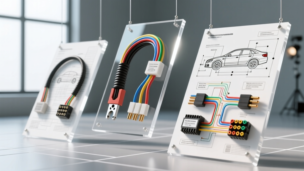
The True Cost of Interpreting Wiring Diagram Symbols
Understanding wiring diagram symbols is the foundation of automotive electrical diagnostics, but recognizing a symbol on a schematic is only half the battle. The true barrier to entry for professional-level troubleshooting is the financial and technical investment required to test the components those symbols represent. Reading a symbol for a Pulse Width Modulated (PWM) solenoid or a Hall-effect sensor is straightforward; accurately measuring a 320Hz duty cycle or a 5V digital square wave without loading the circuit requires specialized, often expensive, diagnostic equipment.
For independent repair shops and advanced DIY technicians, bridging the gap between schematic theory and physical circuit validation requires a strategic approach to tool acquisition. This analysis breaks down the cost and tool requirements necessary to properly test the most common and complex automotive wiring diagram symbols, ensuring your diagnostic budget is allocated toward equipment that yields the highest return on investment.
The Diagnostic Tool Investment Matrix
Before diving into specific symbols, we must establish the baseline costs of an automotive electrical diagnostic bay. Relying solely on a basic $20 digital multimeter (DMM) will lead to misdiagnoses when dealing with modern multiplexed networks or high-speed sensor circuits.
- Automotive DMM (e.g., Fluke 88V): ~$400. Essential for basic voltage drop, resistance, and continuity testing. Features low-impedance (LoZ) modes to eliminate ghost voltages.
- Automotive Oscilloscope (e.g., Picoscope 4225A): ~$1,500. Mandatory for visualizing wiring diagram symbols representing AC generators, PWM solenoids, and CAN-bus networks.
- OEM Breakout Boxes: ~$150 - $300 per manufacturer. Required to safely back-probe ECU/PCM connectors without piercing wires or spreading terminal pins.
- Thermal Imaging Camera (e.g., Fluke TiS60+): ~$600. Used to locate hidden resistance in splices and grounds that are buried deep within harness looms.
Mapping Wiring Diagram Symbols to Required Tooling
Every symbol on an OEM schematic dictates a specific testing methodology. Below is a cost-to-tool analysis for the most critical symbols you will encounter in late-model vehicle wiring diagrams.
| Schematic Symbol | Component Type | Required Diagnostic Tool | Avg Tool Cost | Real-World Testing Scenario |
|---|---|---|---|---|
| Variable Resistor | Throttle Position Sensor (TPS) | Graphing Multimeter / Scope | $400 - $1,500 | Backprobing the 5V reference, ground, and signal return to watch for micro-second voltage dropouts during a Wide Open Throttle (WOT) sweep. |
| Twisted Pair / Shield | High-Speed CAN Bus (HS-CAN) | 2-Channel Oscilloscope + BNC | $1,200+ | Measuring differential voltage on OBD2 Pins 6 and 14 to verify the 2.5V resting state and dominant/recessive bit transitions. |
| Zener Diode | Alternator Field Clipping | Scope w/ Advanced Triggering | $1,500 | Capturing inductive kickback spikes exceeding 40V that a standard DMM will completely miss, preventing false PCM condemnations. |
| Splice (e.g., S142) | Harness Junction Point | Thermal Imaging Camera | $600 | Locating a hidden, corrosion-induced voltage drop inside a loom wrapped in Tesa tape without stripping the entire harness. |
| 120-Ohm Resistor | CAN-Bus Termination | DMM (Ohms) + Breakout Box | $550 | Verifying network termination resistance at the PCM and TCM modules to diagnose U-codes without unplugging live modules. |
The Hidden Cost of OEM Schematic Access
You cannot interpret wiring diagram symbols if you do not have access to the diagrams themselves. While aftermarket software provides a baseline, they often abbreviate connector end-views or omit internal module splice locations. According to industry standards highlighted by Motor Magazine, professional technicians must frequently rely on OEM portals for complete schematic accuracy.
Software Subscription Costs
- ALLDATA / Mitchell1: $170 - $220 per month. Excellent for general symbols and component locations, but may lack internal ECU logic diagrams.
- OEM Short-Term Passes (GM TIS, Toyota TIS, Ford PTS): $30 - $50 for 48-hour access. This is a mandatory micro-cost when you need to view the exact pinout of a 70-pin Ford PCM connector or trace a proprietary LIN-bus network symbol that aftermarket software fails to decode.
Case Study: Tracing a CAN-Bus Fault via Schematic Symbols
Let us examine the financial and technical implications of the twisted pair and termination resistor symbols found on High-Speed CAN (HS-CAN) schematics. When a vehicle presents a U0100 (Lost Communication with ECM) code, the wiring diagram will show a twisted pair symbol connecting the PCM to the OBD2 diagnostic link connector (DLC), typically terminating at Pins 6 (CAN-H) and 14 (CAN-L).
The diagram will also feature two 120-ohm resistor symbols: one inside the PCM block and one inside the TCM or BCM block. If you measure across Pins 6 and 14 with the battery disconnected, your DMM should read exactly 60 ohms (the parallel equivalent of two 120-ohm resistors). If you read 120 ohms, the schematic tells you exactly which module's termination resistor is offline.
The Cost of Improper Probing Techniques
OEM CAN-bus wiring is typically 22 AWG or 20 AWG to save weight and reduce harness bulk. If a technician uses a standard 18 AWG piercing probe to test these wires, they will permanently deform the copper strands and compromise the twisted geometry. This introduces crosstalk and impedance mismatches, potentially causing a $1,200 harness replacement. The correct, cost-effective approach is to use a $25 set of T-pin backprobes or a $150 OEM DLC breakout box, preserving the integrity of the 22 AWG conductors while capturing the differential voltage waveforms outlined by Pico Technology automotive diagnostic guidelines.
Furthermore, wire colors vary drastically by manufacturer. A GM HS-CAN network typically utilizes Dark Green (CAN-H) and Dark Blue (CAN-L). Conversely, a Ford HS-CAN network uses White (CAN-H) and Light Blue (CAN-L). Misidentifying these based on generic assumptions rather than reading the specific wiring diagram symbols and color codes will lead to hours of wasted diagnostic time.
Ground Distribution Symbols and Voltage Drop Testing
The ground symbol (often a downward-pointing arrow or a series of decreasing horizontal lines) accompanied by a designation like G103 or G201 is arguably the most financially significant symbol on any schematic. Modern ECUs do not ground sensors internally; they provide a 5V reference, a signal return, and rely on the engine block or chassis ground to complete the circuit.
If a technician ignores the G103 symbol and assumes the ground is perfect, they might replace a $350 Mass Air Flow (MAF) sensor or a $800 PCM due to a skewed voltage reading. The cost to properly test this symbol? A $15 set of heavy-duty 10 AWG jumper wires with alligator clips. By performing a voltage drop test across the ground circuit (from the sensor ground pin to the battery negative terminal) while the circuit is under load, a reading above 0.1V indicates a faulty ground. Cleaning the G103 location with a wire brush costs pennies and saves hundreds of dollars in misdiagnosed parts.
Shielded Wire Symbols: The Cost of Proper Repair
When a wiring diagram displays a dashed line encircling a set of wires, it indicates a shielded harness. This is common in crankshaft position sensor (CKP) circuits and high-speed data lines to prevent Electromagnetic Interference (EMI) from ignition coils and alternators.
If a repair is required, simply soldering the wires and wrapping them in standard electrical tape violates the schematic's design intent. The EMI will infiltrate the unshielded gap, causing the CKP signal to drop out at high RPMs, leading to a misfire or no-start condition. To properly honor the shielded wire symbol, a technician must invest in copper foil shielding tape (~$30/roll) and solder-sleeve shield splices (~$2 each). While this increases the consumable cost of a $5 wire repair by roughly $15, it guarantees the circuit operates within the parameters defined by SAE International standards, preventing costly comebacks and diagnostic dead-ends.
Conclusion: ROI on Schematic-Driven Tooling
Interpreting wiring diagram symbols is not merely an academic exercise; it is a financial roadmap. Every symbol dictates the necessary tooling, from $400 graphing multimeters for potentiometers to $1,500 oscilloscopes for multiplexed networks. By aligning your tool purchases and software subscriptions with the specific symbols you encounter most frequently in your bay, you transform schematic reading from a theoretical skill into a highly profitable, definitive diagnostic process.