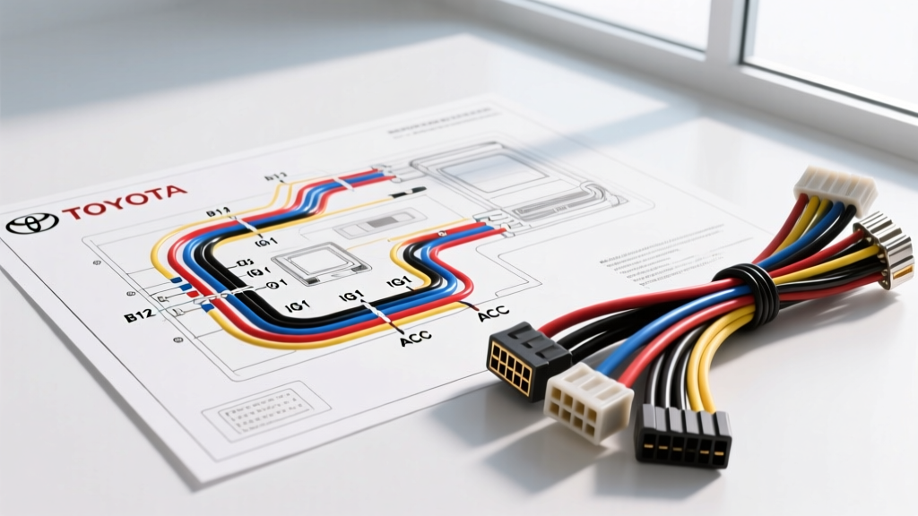
Demystifying the Toyota Wiring Diagram for Radio Installs
When upgrading the head unit in a Toyota, Tacoma, Camry, or 4Runner, the factory wiring schematic can look like an intimidating web of multiplexed data lines and obscure color codes. Unlike older domestic vehicles that relied on simple analog 12-volt triggers, modern Toyota audio systems integrate heavily with the vehicle's CAN-bus (Controller Area Network) and body control modules. However, by understanding the fundamental architecture of a Toyota wiring diagram for radio applications, beginners can confidently navigate harness adapters, verify pinouts, and avoid catastrophic short circuits.
This guide breaks down the essential building blocks of Toyota automotive electrical schematics, focusing specifically on the head unit, speaker outputs, and ancillary data connections. Whether you are installing an aftermarket double-DIN receiver or troubleshooting a silent factory JBL amplifier, mastering these fundamentals is your first step toward a professional-grade installation.
The JIS Color Code System: Reading Toyota Wire Insulation
One of the most confusing aspects for beginners reading a Toyota factory service manual is the wire color nomenclature. Toyota utilizes the Japanese Industrial Standard (JIS) for wire coloring, which differs significantly from the DIN or SAE standards used by European and American manufacturers. In a Toyota schematic, colors are abbreviated using specific letters.
Base Colors and Tracer Stripes
A solid wire is represented by a single letter. A wire with a tracer (stripe) is represented by two letters: the base color first, followed by the tracer color. For example, L-Y translates to a Blue wire with a Yellow stripe. Here is the definitive JIS color key you will encounter in your radio diagrams:
- B = Black
- W = White
- R = Red
- L = Blue
- G = Green
- Y = Yellow
- BR = Brown
- O = Orange
- P = Pink
- V = Violet
- SB = Sky Blue
- LG = Light Green
When tracing a circuit on your diagram, always verify the base color first with your flashlight, then look for the spiral or longitudinal tracer stripe. Misidentifying a B-W (Black/White) wire as a solid W (White) wire is a common beginner error that can lead to miswiring the illumination or accessory circuits.
Standard Toyota Radio Harness Pinouts
Toyota has historically relied on the EIAJ (Electronic Industries Association of Japan) standard for their primary 10-pin radio connectors, though newer models utilize a combination of a 10-pin power/speaker block and a larger 28-pin data/CAN-bus block. Below is the standard pinout for the foundational 10-pin power and speaker harness found in decades of Toyota vehicles.
| Pin | Function | Typical JIS Color | AWG | Circuit Notes |
|---|---|---|---|---|
| 1 | +B (Constant 12V) | L-W (Blue/White) | 16 | Memory / Presets. Tied to DOME or AM2 fuse. |
| 2 | ACC (Ignition) | GR (Gray) | 18 | Switched 12V. Tied to GAUGE or IGN fuse. |
| 3 | GND (Ground) | BR (Brown) | 16 | Chassis Ground. Must read <0.1 ohms to battery negative. |
| 4 | ILL (Illumination) | G-W (Green/White) | 20 | Dash lighting rheostat circuit (0V to 12V dimming). |
| 5 | MUTE / TEL | P (Pink) | 22 | Often unused in base models; mutes audio for BT calls. |
| 6 | PWR ANT / AMP | B-R (Black/Red) | 18 | Remote turn-on for external amps or power antenna. |
| 7 | FL+ (Front Left +) | P (Pink) | 18 | Positive speaker output. |
| 8 | FL- (Front Left -) | V (Violet) | 18 | Negative speaker output (Do not ground). |
| 9 | FR+ (Front Right +) | LG (Light Green) | 18 | Positive speaker output. |
| 10 | FR- (Front Right -) | O (Orange) | 18 | Negative speaker output (Do not ground). |
Note: Rear speaker pins are typically located on an adjacent 6-pin or 8-pin secondary connector, or integrated into the larger 28-pin harness on newer infotainment systems.
Wire Gauges (AWG) and Current Carrying Capacity
Understanding wire gauge is critical when splicing or replacing damaged harness segments. Toyota's low-tension primary cables adhere to standards similar to those outlined in SAE International J1128. The insulation thickness and copper stranding dictate the wire's ability to handle current without voltage drop or overheating.
- 16 AWG (approx. 1.5mm²): Used for main power (+B), ground (GND), and high-draw accessory circuits. Capable of handling up to 10-12 amps continuously.
- 18 AWG (approx. 0.75mm²): The standard for speaker outputs and switched accessory (ACC) lines. Rated for roughly 7-9 amps. Never use 18 AWG for a main constant 12V feed on a high-power aftermarket amplifier.
- 20 to 22 AWG (approx. 0.5mm² to 0.35mm²): Reserved for low-current signal wires, such as illumination (ILL), steering wheel control (SWC) voltage ladders, and CAN-bus data lines.
Steering Wheel Controls (SWC) and CAN-Bus Integration
Modern Toyota wiring diagrams for radio installs are incomplete without addressing the steering wheel controls. Older Toyota models (pre-2010) utilized a simple analog resistor ladder network. When you press the 'Volume Up' button, it completes a circuit through a specific resistor, dropping the voltage on the SWC wire (often Pin 14 or 15 on the 28-pin connector). Aftermarket interfaces read this voltage drop and translate it into an IR or data command for the new radio.
Newer Toyotas utilize CAN-bus (Controller Area Network) for SWC. You will see CAN-H (usually White, W) and CAN-L (usually Black, B) twisted pair wires on the schematic. These operate at roughly 2.5V and 1.5V respectively. Never probe CAN-bus wires with a standard test light or an unbuffered multimeter on continuity mode, as this can crash the vehicle's body control module network. Always use a high-impedance digital multimeter or an automotive logic probe.
Grounding Conventions and Splice Packs
Toyota schematics do not just show a generic ground symbol; they designate specific ground points using a standardized nomenclature. Understanding this helps you trace where a harness physically terminates in the dash.
- IE (Instrument Earth/Panel Ground): Located behind the dash, kick panels, or steering column bracket (e.g., IE1, IE2). The radio's main brown ground wire typically terminates here.
- BE (Body Earth): Located on the metal body shell, often under carpets or in door sills.
- RE (Roof Earth): Used for overhead consoles and antennas.
When a Toyota diagram shows a solid black circle on a wire line, it indicates a Splice Pack or solder joint inside the harness tape. If your aftermarket radio is blowing the DOME fuse immediately upon connection, consult the diagram to see if the +B wire shares a splice pack with a shorted accessory (like a blown map light or aftermarket dashcam) further down the harness.
Common Beginner Mistakes and Troubleshooting
Even with the correct harness adapter from a trusted source like the Crutchfield Toyota Fit Guide, beginners frequently encounter specific failure modes. Here is how to diagnose them using your schematic and a multimeter:
1. Radio Turns On, But Presets Reset Every Time the Car is Turned Off
The Cause: Swapped +B (Constant) and ACC (Switched) wires.
The Fix: The aftermarket radio harness adapter was wired backward. The yellow wire on the aftermarket radio must connect to the Toyota +B (Pin 1), and the red wire must connect to the Toyota ACC (Pin 2). Use your multimeter to test the vehicle-side plug with the key OFF. The pin that reads 12.6V continuously is your +B.
2. Radio Powers On, But No Sound (JBL Equipped Vehicles)
The Cause: Missing JBL amplifier wake-up signal.
The Fix: In premium JBL systems, the factory radio does not send a 12V remote turn-on signal to the amplifier. Instead, it sends a digital wake-up command via the CAN-bus or a specific data pin. If you use a basic analog wiring harness, the JBL amp in the trunk or under the seat will never turn on. You must use a specialized interface (such as an Axxess TYTO-01 or Metra AFDI-5V) that intercepts the data and generates the 12V remote turn-on required by your aftermarket radio's blue/white wire.
3. Blown 'AM2' or 'DOME' Fuse Upon Connection
The Cause: Pinched wire or short to ground in the dash cavity.
The Fix: When pushing the new radio into the dash, the sharp metal edges of the DIN sleeve or radio chassis can slice into the 16 AWG +B or ILL wires. Consult your Haynes Toyota Repair Manual to locate the exact fuse box position, replace the blown fuse, and wrap the harness in Tesa tape or split-loom tubing before final insertion to prevent chassis shorts.
Final Thoughts on Schematic Literacy
Reading a Toyota wiring diagram for radio installs does not require an electrical engineering degree, but it does demand respect for the vehicle's specific color codes, gauge limitations, and multiplexed data networks. By taking the time to verify pinouts with a multimeter, understanding the JIS color abbreviations, and recognizing the difference between analog triggers and CAN-bus signals, you transform a frustrating guessing game into a precise, professional installation.