Executing the Street-to-Track Daytona 675 Conversion
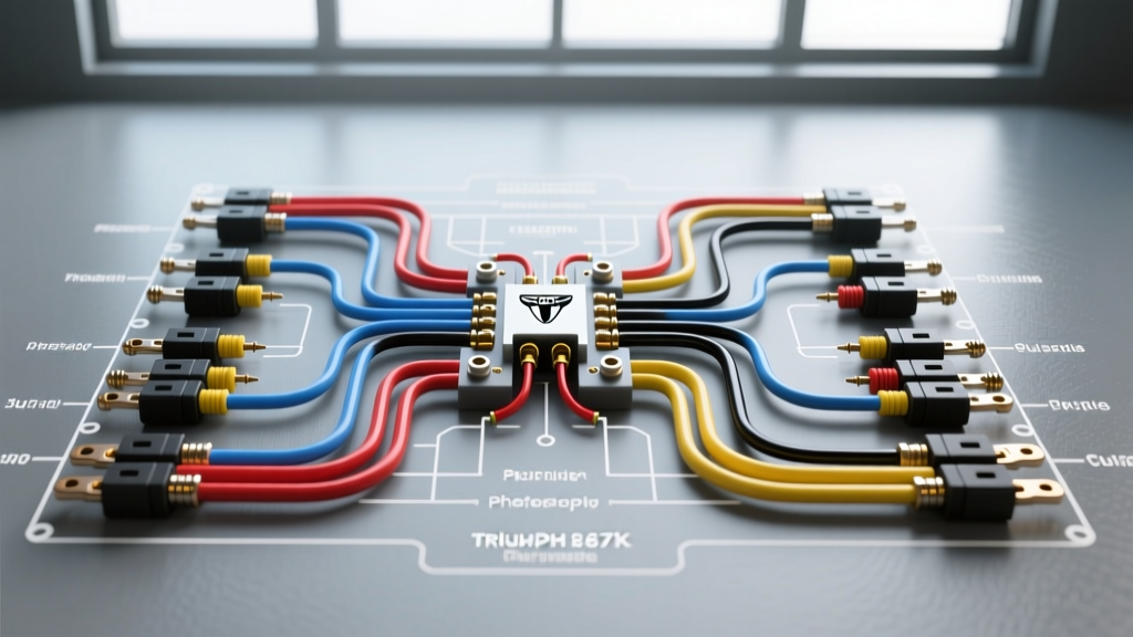
Transforming a street-legal Triumph Daytona 675 into a dedicated track weapon requires far more than just stripping off the mirrors and taping the headlights. The electrical architecture of the 675, particularly the 2006-2012 Keihin ECU generations, is deeply integrated with emissions controls, the HISS immobilizer, and complex CAN-bus instrument clusters. When building a race harness or installing advanced data logging systems, securing an accurate triumph daytona 675 wiring pinout diagram pdf is the first critical step to avoid catastrophic electrical shorts or bricking the ECU.
Unlike modern ride-by-wire systems that lock down access to core ignition maps, the earlier Keihin harnesses offer direct, analog-style access to ignition coil grounds and fuel injector triggers. This makes them a favorite among amateur superbike racers and custom fabricators. However, modifying the main harness requires a meticulous understanding of cavity pinouts, wire gauge (AWG) requirements, and sealed connector standards. This guide provides the technical foundation for executing high-level electrical modifications on the Daytona 675 platform.
Keihin 34-Pin Main ECU Connector: Critical Pinout Specifications
The heart of the Daytona 675 electrical modification project is the main 34-pin sealed connector linking the engine harness to the Keihin ECU. When splicing in aftermarket quickshifters, wideband O2 controllers, or auxiliary data loggers, you must intercept specific circuits without compromising the ECU's internal drivers. Below is a targeted reference table for the most frequently modified pins.
| Pin Cavity | Circuit Function | OEM Wire Color | AWG | Modification Target |
|---|---|---|---|---|
| 1 | Main Relay Power (12V+) | Red/White | 18 AWG | Switched power trigger for data loggers |
| 12 | Injector 1 Trigger | Green/Red | 20 AWG | Fuel cut/splicer integration |
| 13 | Injector 2 Trigger | Green/White | 20 AWG | Fuel cut/splicer integration |
| 14 | Injector 3 Trigger | Green/Black | 20 AWG | Fuel cut/splicer integration |
| 24 | CAN-Bus High (CAN-H) | White/Red | 22 AWG | Aftermarket dash / GPS module |
| 25 | CAN-Bus Low (CAN-L) | White/Black | 22 AWG | Aftermarket dash / GPS module |
| 28 | Ignition Coil 1 Ground | Black/White | 20 AWG | Ignition-kill quickshifter splice |
| 29 | Ignition Coil 2 Ground | Black/Red | 20 AWG | Ignition-kill quickshifter splice |
| 30 | Ignition Coil 3 Ground | Black/Yellow | 20 AWG | Ignition-kill quickshifter splice |
| 34 | Main ECU Ground | Black | 16 AWG | Supplemental chassis grounding |
Intercepting the Ignition Circuit for Quickshifters
For track upgrades, installing an ignition-kill quickshifter (such as those from Translogic or HM Racing) is standard procedure. While modern kits use strain-gauge load cells, the electrical interruption still requires splicing into the ignition coil ground wires (Pins 28, 29, and 30). Never splice into the 12V+ power feed of the coils. Interrupting the high-current power side generates massive inductive voltage spikes that will instantly destroy the Keihin ECU's internal ignition drivers. Always intercept the ground side using 22 AWG MIL-W-22759/16 Tefzel wire, and ensure the quickshifter's internal MOSFET is rated for the combined inductive load of the three Daytona 675 pencil coils.
Instrument Cluster Bypass and CAN-Bus Termination
When stripping a Daytona 675 for a lightweight race harness, the heavy OEM instrument cluster and its associated sub-harness are usually discarded. However, the Keihin ECU expects to see a functioning CAN-bus network. If the ECU cannot communicate with the dash, it may trigger a Check Engine Light (CEL), default to a restrictive limp-home fuel map, or disable the cooling fan relay.
To properly delete the OEM dash, you must terminate the CAN-bus circuit at the main harness. Locate Pins 24 (White/Red) and 25 (White/Black) on the ECU side of the harness. Solder a precision 120-ohm, 1/4-watt metal film resistor directly across these two wires. This fools the ECU into believing the network is intact and properly terminated, preventing CAN-bus timeout errors. Seal the resistor in marine-grade heat shrink with adhesive lining to prevent vibration-induced fracturing on the track.
HISS Immobilizer Defeat for Race Harnesses
The Triumph HISS (High Integrity Security System) immobilizer is a major hurdle when building a standalone race harness or swapping ECUs between track chassis. The HISS ring antenna surrounds the ignition barrel and communicates via a proprietary low-frequency RF signal to the ECU. If you are building a keyless race harness, you have two options:
- Option A (The Clean Method): Use a tuning software suite like TuneECU to permanently disable the immobilizer function within the ECU's firmware. Once flashed, the ECU will no longer poll for the HISS transponder, allowing you to completely remove the ring antenna and ignition switch wiring.
- Option B (The Hardware Method): If the ECU cannot be flashed to delete HISS, you must cut the ring antenna from a donor key harness, embed a programmed HISS transponder chip inside the antenna ring, and zip-tie the assembly permanently beneath the airbox. The ECU will read the chip continuously and allow the engine to start via a simple toggle switch.
Wiring Standards: AWG, Insulation, and Connectors
The engine bay of a Daytona 675 routinely sees ambient temperatures exceeding 140°F (60°C) near the stator and exhaust headers. Standard PVC-insulated wire will become brittle, crack, and cause intermittent short circuits. All replacement wiring and pigtails must adhere to SAE J1128 and ISO 6722 standards for high-temperature automotive applications.
- Wire Insulation: Exclusively use cross-linked ETFE (Tefzel) or PTFE (Teflon) insulated wire. It withstands continuous temperatures up to 200°C and is highly resistant to race fuel and oil exposure.
- Connectors: The OEM harness utilizes Sumitomo HM 090 series sealed connectors. When extending harnesses for rearsets or relocated ECUs, use matching Sumitomo cavities and seals. For aftermarket accessories (like auxiliary cooling pumps or GPS modules), utilize Deutsch DTM or DT series connectors, which offer superior vibration resistance and silicone wire seals.
- Crimping: Never solder wires in high-vibration motorcycle harnesses. Solder creates a rigid point that will fatigue and snap under chassis flex. Use a proper ratcheting open-barrel crimper (like the Deutsch AFM8) to achieve a cold-weld gas-tight crimp.
Troubleshooting Common ECU Mod Failures
Even with a perfect triumph daytona 675 wiring pinout diagram pdf, track modifications introduce new failure points. Here is a diagnostic decision tree for common post-modification electrical gremlins:
- Symptom: Engine cranks but will not fire; fuel pump does not prime.
Cause: The HISS system is active and no transponder is detected, OR the side-stand switch bypass is wired incorrectly.
Fix: Verify the side-stand switch circuit (usually Pink/White to Ground) is permanently bridged. Check HISS status via diagnostic software. - Symptom: Random misfires at high RPM (above 11,000) only under load.
Cause: Voltage drop on the ignition coil power feed due to undersized wire or a corroded main ground.
Fix: Measure voltage at the coil positive terminal while cranking. If it drops below 10.5V, upgrade the coil power feed to 16 AWG and add a dedicated ground strap from the engine block to the battery negative terminal. - Symptom: Aftermarket dash shows erratic RPM or drops offline on the straights.
Cause: CAN-bus electromagnetic interference (EMI) from the stator or high-tension ignition leads.
Fix: Ensure the CAN-H and CAN-L wires are routed as a twisted pair (minimum 2 twists per inch) and are physically separated from the stator output wires by at least 2 inches.
Authoritative Resources and Schematics
To execute these modifications safely, always cross-reference your physical harness with the factory documentation. Wiring colors can vary slightly between the 2006-2008 and 2009-2012 model years due to mid-generation harness revisions. Consult the official Triumph Daytona 675 Service Manual (Section 9: Electrical Systems) for complete chassis-to-ECU routing diagrams. Additionally, utilizing TuneECU is mandatory for verifying sensor inputs, testing fuel pump relays, and confirming immobilizer status after completing your physical wiring upgrades.