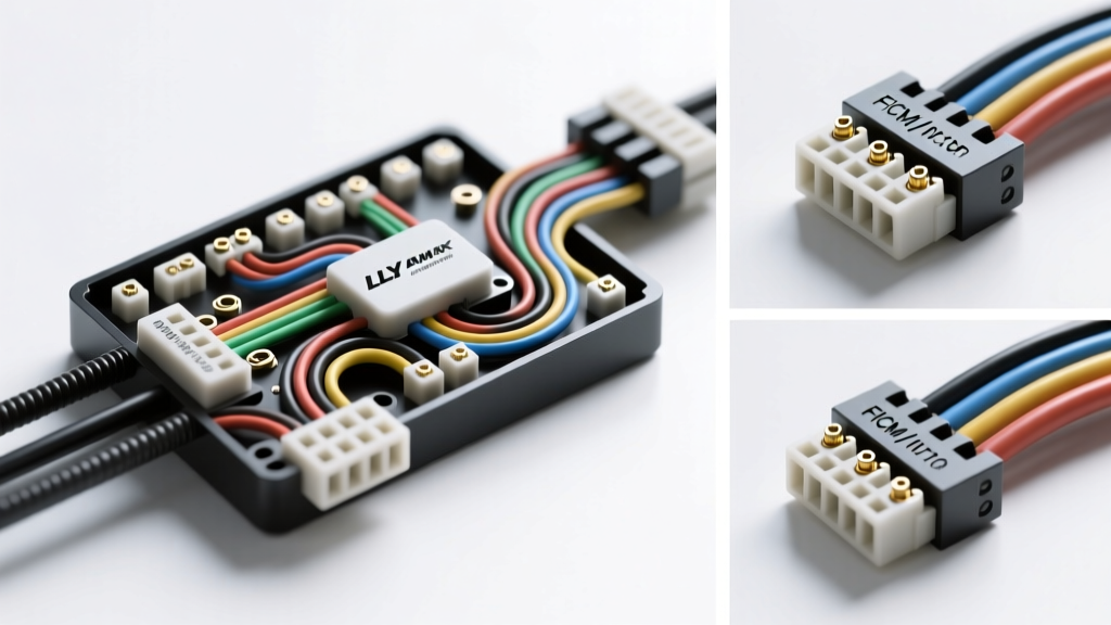
Understanding the LLY Duramax Electrical Architecture
The 2004.5-2005 LLY Duramax 6.6L V8 introduced significant revisions to the GM heavy-duty diesel platform, most notably in its fuel delivery and engine management electronics. Unlike its predecessor, the LB7, the LLY utilizes a revised Fuel Injection Control Module (FICM) mounting location and a completely unique injector wiring harness routing. For diesel technicians and DIY enthusiasts, interpreting the LLY Duramax wiring harness diagram is critical, as the physical routing of these harnesses is notorious for causing premature chafing, short-to-ground faults, and intermittent injector circuit Diagnostic Trouble Codes (DTCs).
This practical installation guide bridges the gap between the factory schematic and real-world wrenching. Whether you are replacing a degraded FICM pigtail, upgrading your alternator sense wire, or installing a complete OEM replacement injector harness, understanding the specific AWG requirements, pin configurations, and torque specifications is mandatory for a reliable repair.
Decoding the LLY Duramax Wiring Harness Diagram
The LLY injector harness acts as the bridge between the FICM (mounted on the driver-side valve cover) and the eight fuel injectors. The FICM steps up the 12V vehicle system voltage to the high voltage required to actuate the injector solenoids. When reading the factory GM service wiring diagram, you will focus primarily on the FICM Connector C1 (Injector Control) and the main power/ground feeds.
Below is a condensed reference table for the FICM Connector C1 injector control pins. Note that GM uses specific High-Temperature Cross-Linked (TXL) wire for these circuits to withstand the extreme radiant heat of the LLY turbocharger and exhaust manifolds.
| FICM Pin (C1) | Circuit Function | Wire Color | AWG Size | Destination |
|---|---|---|---|---|
| 1 | Injector 1 Control | Dark Blue | 18 AWG TXL | Cyl 1 Injector |
| 2 | Injector 1 Return | Black/White | 18 AWG TXL | Cyl 1 Injector |
| 3 | Injector 2 Control | Gray | 18 AWG TXL | Cyl 2 Injector |
| 4 | Injector 2 Return | Black/White | 18 AWG TXL | Cyl 2 Injector |
| 5 | Injector 3 Control | Light Blue | 18 AWG TXL | Cyl 3 Injector |
| 11 | Injector 6 Control | Purple | 18 AWG TXL | Cyl 6 Injector |
| 12 | Injector 6 Return | Black/White | 18 AWG TXL | Cyl 6 Injector |
Note: Pins 6-10 and 13-16 follow the sequential firing order pattern. Always verify against your specific VIN-derived GM service manual, as mid-year running changes occurred in 2005.
Common LLY Harness Failure Points
Before installing a new harness, you must address the physical environment that destroyed the original. According to Haynes GM Silverado/Sierra Repair Manuals and field data, the LLY suffers from three primary harness failures:
- The Alternator Chafe Point: The main injector harness drops down behind the alternator bracket. Vibration causes the split-loom to wear through, allowing the 18 AWG injector control wires to short against the grounded alternator casing. This instantly triggers P0201-P0208 codes and can fry the FICM driver circuit.
- FICM Connector Water Ingress: The cowl seal above the driver-side valve cover frequently leaks, dripping water directly onto the FICM C1 and C2 connectors, leading to green copper oxide corrosion and high-resistance faults.
- Alternator Sense Wire Degradation: The OEM 16 AWG red sense wire running from the alternator to the ECM/underhood fuse block suffers from voltage drop due to heat and micro-fractures, causing the LLY to undercharge at idle.
Step-by-Step LLY Injector Harness Replacement Guide
Follow this procedure to install a new OEM-spec LLY injector harness while eliminating the factory routing flaws.
Phase 1: Preparation and Extraction
- Depower the System: Disconnect both negative battery cables. The LLY uses a dual-battery setup; leaving the passenger side connected can retain enough capacitance in the FICM to cause an arc upon connector removal.
- Remove the Intake Plenum: Unbolt the plastic intake plenum (10mm bolts) to expose the rear of the engine and the passenger-side valve cover.
- Disconnect FICM Connectors: Press the release tab on the FICM C1 and C2 connectors. Do not pull by the wires. Use a plastic pick to release the secondary locking wedge if equipped.
- Unclip Injector Pigtails: Squeeze the metal retaining tabs on the injector solenoid connectors. Use a 90-degree pick tool to gently pry the connectors upward. Never twist the connectors, as the internal O-rings will tear.
- Remove Harness Brackets: Remove the 10mm bolts securing the harness brackets to the valve covers and the rear engine lift bracket.
Phase 2: Upgraded Routing and Looming
- Apply Tesa Tape: Wrap the new harness entirely in Tesa 51036 PET cloth tape. This provides superior abrasion resistance and eliminates the rattling noise associated with hard plastic split-loom.
- Install Heat Shielding: Where the harness passes near the turbocharger exhaust housing and the EGR cooler, slide on a silicone-coated fiberglass heat sleeve rated for 1000°F.
- Address the Alternator Chafe: Before routing the harness behind the alternator, apply a piece of self-adhesive closed-cell foam or a rubber U-channel edge guard to the sharp metal lip of the alternator mounting bracket.
Phase 3: Installation and Torquing
- Route and Clip: Lay the harness into the factory valley channel. Ensure the injector drops are aligned with their respective cylinders without any tension or sharp bends (maintain a minimum bend radius of 1 inch for 18 AWG TXL wire).
- Connect Injectors: Push the injector connectors on until you hear a definitive click. Verify the metal retaining clip is fully seated.
- Apply Dielectric Grease: Apply a liberal amount of silicone dielectric grease to the FICM C1 and C2 connectors before mating them to the module. This prevents moisture ingress and galvanic corrosion.
- Torque Specifications:
- FICM to Valve Cover Bolts: 10 Nm (89 lb-in)
- Harness Bracket to Engine Block: 12 Nm (106 lb-in)
- Intake Plenum Bolts: 10 Nm (89 lb-in)
Upgrading the LLY Alternator and Battery Cables
While the harness is apart, address the LLY's chronic charging system weaknesses. The OEM battery cables are typically 2/0 AWG, but voltage drop across the factory parallel setup is common. Upgrade your main battery cables to 4/0 AWG fine-strand copper, adhering to the SAE J1127 Battery Cable Standard for heavy-duty diesel applications.
Furthermore, replace the factory alternator sense wire. Splice in a new 10 AWG TXL red wire directly from the alternator sense terminal to a clean, fused ignition-switched 12V source at the underhood fuse block. This eliminates the voltage drop inherent in the OEM wiring and ensures the ECM commands the alternator to output a true 14.2V - 14.8V at idle, which is critical for FICM capacitor charging.
Troubleshooting Decision Tree: Injector Circuit DTCs
If you are installing a harness to chase a fault, use this diagnostic tree to verify your repair:
- Symptom: DTC P0201 (Injector 1 Control Circuit) sets immediately upon key-on-engine-off (KOEO) test.
- Cause: Open circuit or short to ground on Pin 1 or Pin 2 of FICM C1.
- Fix: Perform a pin-drag test on the FICM connector. If the female terminal is expanded, replace the pigtail using a GM Weather-Pack crimp tool. Check the alternator bracket chafe point.
- Symptom: Multiple random injector codes (e.g., P0203, P0206, P0208) setting simultaneously under heavy load.
- Cause: FICM power feed voltage drop or degraded main ground.
- Fix: Load test the FICM 12V power feed and the main engine block ground strap. Clean the ground eyelet on the passenger side cylinder head to bare metal.
- Symptom: Injector codes only appear when the engine is wet or after a car wash.
- Cause: Compromised injector connector O-rings or FICM water ingress.
- Fix: Replace the injector harness assembly and seal the FICM connector boots with marine-grade heat shrink.
Final Expert Insights
Working with the LLY Duramax wiring harness requires patience and an adherence to OEM routing specifications. The introduction of the FICM to the valve cover created a harsh environment for wiring. By utilizing high-temp TXL wire, cloth harness tape, and addressing the known alternator bracket chafe points during your installation, you will effectively eliminate the most common electrical failures of the 2004.5-2005 platform. Always reference the latest GM Technical Service Bulletins (TSBs) regarding FICM calibration updates after completing any major harness replacement.