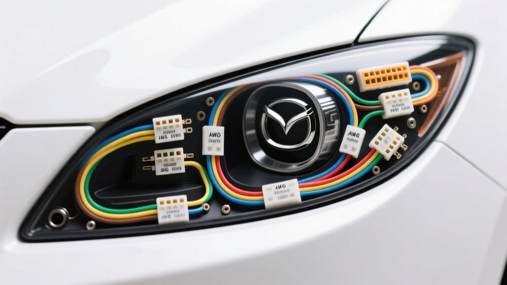
2010 Mazda 6 Headlight Electrical Architecture Overview
The 2010 Mazda 6 (second-generation GH chassis, facelift era) utilizes a centralized Body Control Module (BCM) and dedicated lighting relays to manage the front exterior lighting circuits. When diagnosing or replacing the 2010 Mazda 6 headlight wiring harness, technicians must account for the specific Yazaki and Sumitomo sealed connectors used by Mazda, as well as the exact wire color codes and American Wire Gauge (AWG) ratings mandated by the manufacturer. Unlike newer vehicles that rely heavily on multiplexed CAN-bus lighting networks, the 2010 model year primarily uses hardwired, relay-switched 12V circuits for the primary headlamp functions, making traditional voltage-drop testing and harness continuity checks highly effective.
This technical specification reference covers the main chassis-to-headlight connector pinouts, individual bulb pigtail harness specifications, common thermal failure modes, and precise repair methodologies compliant with SAE J1128 standards for low-tension primary automotive cables.
Main Chassis-to-Headlight Connector Pinout (Halogen Trims)
For 2010 Mazda 6 models equipped with standard halogen headlamps (typically Base, Touring, and some Grand Touring trims), the main harness interfaces with the headlight assembly via an 8-pin sealed connector. This connector routes power from the engine bay fuse/relay box to the internal headlight distribution board.
| Pin | Function | Wire Color (Mazda Code) | AWG Size | Circuit Protection |
|---|---|---|---|---|
| 1 | Low Beam Power (H11) | Green/Black (G/B) | 16 AWG | 15A Fuse / Low Beam Relay |
| 2 | High Beam Power (9005/HB3) | Red/Black (R/B) | 16 AWG | 15A Fuse / High Beam Relay |
| 3 | Front Turn Signal Power | Light Green/Black (L/B) | 18 AWG | 15A Hazard/Flasher Module |
| 4 | Parking/Position Light Power | Green/Red (G/R) | 18 AWG | 10A Tail Light Fuse |
| 5 | Primary Ground (Shared) | Black (B) | 14 AWG | N/A (Chassis Ground G14/G15) |
| 6 | Daytime Running Lamp (DRL) Signal | White/Red (W/R) | 18 AWG | BCM Controlled |
| 7 | High Beam Flash (Pass-to-Pass) | Red/Yellow (R/Y) | 16 AWG | Multi-function Switch Relay |
| 8 | Reserved / Shield Drain | --- | --- | --- |
Note: Wire colors may feature a secondary tracer stripe. Always verify against the specific Mazda Service Information Portal wiring diagrams for your exact VIN, as mid-year production changes can alter tracer colors.
Bulb-Specific Pigtail Harness Specifications
The internal headlight harness utilizes specific pigtails for each bulb. Due to the thermal environment inside the headlight housing, these pigtails are frequent points of failure and often require replacement.
H11 Low Beam Pigtail (High-Failure Point)
The H11 low beam bulb draws approximately 4.1 Amps at a standard 13.5V system voltage. While the 16 AWG supply wire is more than adequate for this load, the physical plastic connector housing is prone to thermal degradation. The heat from the 55W halogen bulb base, combined with ambient engine bay temperatures and minor voltage drop across the terminals, causes the standard OEM plastic H11 connector to melt or become brittle.
- Connector Type: H11 / H8 / H9 2-pin sealed female receptacle.
- Wire Gauge: 16 AWG (Minimum). Do not use 18 AWG replacement pigtails, as they increase resistance and exacerbate heating.
- Upgrade Recommendation: Replace failing OEM plastic pigtails with high-temperature ceramic H11 connectors. Ceramic housings dissipate heat effectively and will not melt under continuous 55W loads.
9005 (HB3) High Beam Pigtail
The high beam circuit utilizes a 9005 (HB3) bulb rated at 65W, drawing roughly 4.8 Amps. This circuit is only active intermittently, meaning thermal failure of the plastic pigtail is less common than the H11. However, moisture intrusion leading to terminal corrosion is a frequent issue.
- Connector Type: 9005 / HB3 2-pin locking receptacle.
- Wire Gauge: 16 AWG.
- Terminal Type: Male spade with locking tang. Ensure the locking tang is fully engaged to prevent vibration-induced arcing.
Front Turn Signal (7443) & Parking Light (194) Pigtails
The turn signal utilizes a 7443 (WY21W) wedge-base bulb, while the parking light uses a 194 (W5W) wedge-base bulb. These circuits are often integrated into a shared sub-harness within the headlight assembly.
- Turn Signal Current: ~1.7A (21W). Wire: 18 AWG.
- Parking Light Current: ~0.4A (5W). Wire: 20 AWG or 18 AWG.
- Failure Mode: Wedge-base sockets frequently suffer from terminal tension loss. The brass contacts spread apart over time, causing intermittent flickering. Bending the contacts inward slightly or replacing the entire socket pigtail resolves this.
HID (Xenon) Headlight Harness Variations
Grand Touring trims equipped with factory High-Intensity Discharge (HID) headlights utilize a completely different harness architecture for the low beam circuit. Instead of a direct 12V feed to an H11 bulb, the harness routes power to a high-voltage ballast mounted to the bottom of the headlight housing.
- Ballast Input: Standard 2-pin or 3-pin sealed connector (12V, Ground, and sometimes a CAN-bus feedback line).
- Igniter Output: The ballast sends a 25,000V ignition pulse to the D2S bulb via a specialized high-voltage coaxial cable. WARNING: Never probe the D2S high-voltage harness with a standard digital multimeter. Doing so will destroy the multimeter and poses a severe lethal shock hazard.
- Diagnostics: HID troubleshooting requires swapping ballasts or igniters side-to-side to isolate the fault, rather than performing continuity checks on the high-voltage side.
Diagnostic Decision Tree: Low Beam Inoperative
When diagnosing a dead low beam on the 2010 Mazda 6, follow this systematic decision tree to isolate whether the fault lies in the bulb, the pigtail harness, the main chassis harness, or the BCM/Relay.
- Step 1: Visual Inspection. Remove the H11 bulb. Inspect the plastic pigtail connector for melted terminals or brown scorch marks. If melted, replace the pigtail and bulb (bulb terminals are likely pitted). If intact, proceed to Step 2.
- Step 2: Voltage Check at Pigtail. With the headlights ON, back-probe the pigtail connector. Do you measure 12.0V - 14.0V between the Power (G/B) and Ground (B) wires?
- YES: The harness is functional. Replace the H11 bulb.
- NO (0V): Proceed to Step 3.
- NO (Low Voltage, e.g., 4V-8V): High resistance in the circuit. Perform a voltage drop test on both the power and ground sides of the harness.
- Step 3: Ground Verification. Test for continuity between the pigtail Ground (B) wire and a known good chassis ground. If open, trace the ground wire to the main connector and check for terminal corrosion. If continuity is good, proceed to Step 4.
- Step 4: Main Connector & Relay. Check Pin 1 at the main chassis-to-headlight connector. If 12V is present here but not at the pigtail, the internal headlight distribution board or internal wiring is faulty. If 12V is absent at Pin 1, check the Low Beam Relay and the 15A fuse in the engine bay fuse block. Refer to NHTSA FMVSS 108 lighting standards for compliance requirements when replacing relays or modifying circuits.
Harness Repair & Splicing Best Practices
When replacing a melted H11 pigtail or repairing a chafed wire in the 2010 Mazda 6 headlight wiring harness, standard twist-and-tape methods are unacceptable. The engine bay environment requires moisture-proof, vibration-resistant repairs.
Proper Splicing Procedure
- Strip and Clean: Strip 3/8 inch of insulation from both the OEM harness wire and the replacement pigtail wire. Ensure the wire gauge matches (16 AWG for H11/9005).
- Stagger Cuts: If repairing a multi-wire harness, stagger your cut points by at least 1 inch. This prevents the splice joints from stacking on top of each other, which creates a bulky, rigid spot prone to vibration failure.
- Crimp and Solder: Use a copper barrel crimp, then apply rosin-core solder to the joint. Soldering alone is brittle and will crack under engine vibration; crimping alone can corrode if moisture breaches the seal.
- Adhesive-Lined Heat Shrink: Seal the repair with dual-wall, adhesive-lined polyolefin heat shrink tubing. The inner adhesive layer melts and flows into the wire strands, creating a 100% waterproof seal.
- Dielectric Grease: Apply a small amount of dielectric grease (such as Nyogel 760G) to the connector terminals before mating to prevent oxidation and fretting corrosion.
Ground Point Maintenance (G14 / G15)
The headlight harnesses ground to the radiator support via ground points typically designated as G14 (Left) and G15 (Right). A poor ground will cause the headlights to dim, flicker, or back-feed through other circuits (e.g., high beams glowing dimly when low beams are on). To service these grounds:
- Remove the 10mm ground bolt.
- Clean the metal ring terminal and the chassis mating surface with a wire brush or Scotch-Brite pad until bare, shiny metal is exposed.
- Apply a thin layer of zinc-rich anti-corrosion compound or dielectric grease over the joint after reassembly to prevent future oxidation.
- Torque the ground bolt to 8 Nm (71 in-lbs) to ensure adequate clamping force without stripping the radiator support threads.