Understanding the 6.0L Electro-Viscous Fan Clutch System
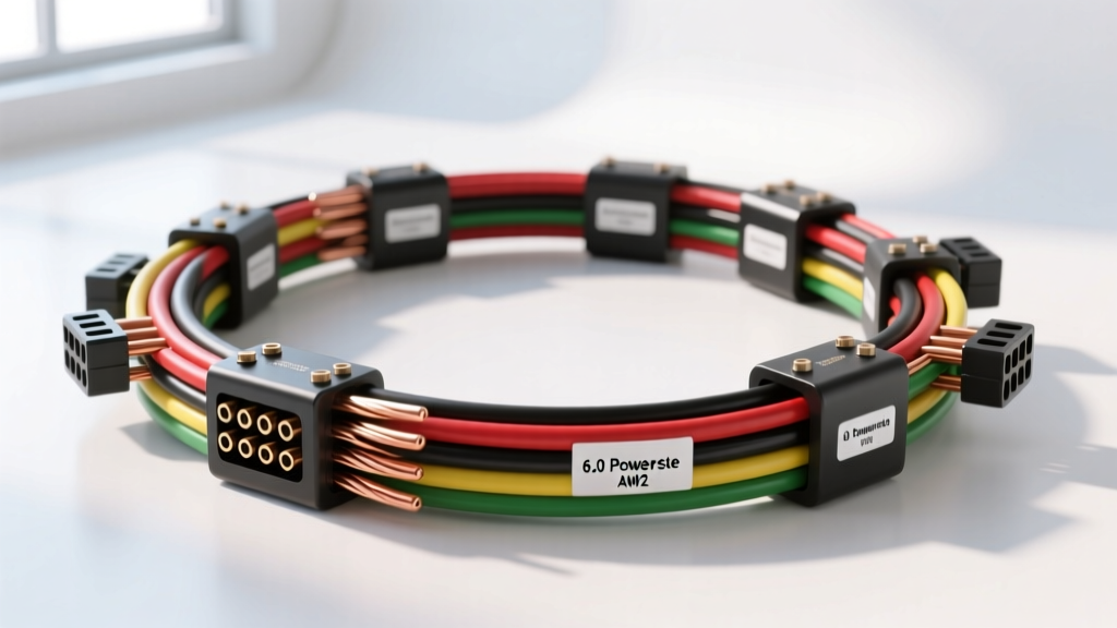
The Ford 6.0L Powerstroke engine, found in 2003-2007 Super Duty trucks and Excursions, relies on a highly sophisticated cooling system to manage the immense heat generated by its high-pressure common rail injection and turbocharging systems. At the heart of this cooling system is the electro-viscous fan clutch. Unlike older mechanical clutches that rely purely on thermal springs, the 6.0L fan clutch is electronically controlled by the Powertrain Control Module (PCM). The PCM monitors coolant temperature, intake air temperature, and AC head pressure, sending a Pulse Width Modulated (PWM) signal through the 6.0 Powerstroke fan clutch wiring harness to engage or disengage the fan dynamically.
For beginners stepping into diesel maintenance, understanding that this fan is not simply 'on' or 'off' is crucial. The PWM signal varies the duty cycle, allowing the PCM to command partial engagement. This means the wiring harness must carry a clean, uninterrupted low-voltage signal. Any resistance, chafing, or corrosion in the harness will alter the duty cycle, leading to catastrophic overheating or unnecessary parasitic drag on the engine.
Common Failure Modes of the Fan Clutch Harness
Before grabbing a replacement pigtail, it is essential to understand why the original harness failed. The 6.0 Powerstroke engine bay is notoriously hostile to electrical components. The fan clutch harness typically fails due to three primary culprits:
- Thermal Degradation: The harness routes dangerously close to the degas bottle, the upper radiator hose, and the turbocharger pedestal. Over years of heat cycling, the standard PVC or cross-linked insulation becomes brittle, cracks, and exposes the copper strands.
- Vibration and Chafing: The 6.0L is a high-vibration engine. If the harness is not properly secured in its factory loom and retainers, it will rub against the aluminum radiator support or the fan shroud, eventually wearing through the insulation and shorting to ground.
- Terminal Fretting Corrosion: The connector at the fan clutch itself is exposed to water splash, road salt, and fine dust. Without proper dielectric grease, moisture infiltrates the connector, causing micro-corrosion on the terminals. This increases resistance, which the PCM interprets as a circuit fault, often triggering a P0480 (Fan Clutch Control Circuit Malfunction) diagnostic trouble code.
OEM Wiring Specifications and PCM Pinout Chart
When repairing or fabricating a section of the 6.0 Powerstroke fan clutch wiring harness, you must adhere to strict automotive electrical standards. Using household wire or incorrect gauges will lead to voltage drop and PCM driver failure. According to SAE J1128 standards for low-tension primary cable, you must use Cross-Linked Polyethylene (TXL or GXL) wire, which is rated for high-temperature engine bay environments.
| PCM Pin / Connector | Wire Color (OEM) | Wire Gauge (AWG) | Circuit Function |
|---|---|---|---|
| PCM Pin 86 (Connector C1381b) | White/Red (WH/RD) or Yellow/Light Green | 18 AWG TXL | Fan Clutch PWM Control Signal |
| Fan Clutch Connector Pin 2 | Black/Yellow (BK/YE) or Black | 18 AWG TXL | Fan Clutch Ground / Return Circuit |
| Chassis Ground Point | Black (BK) | 14 AWG TXL | Main Ground Reference (if repairing ground loop) |
Note: Wire colors can vary slightly between early (2003-2004) and late (2005-2007) 6.0L models due to mid-year PCM calibration updates. Always verify with a multimeter against your specific vehicle's wiring diagram.
Step-by-Step Harness Replacement Fundamentals
Replacing the fan clutch pigtail is a beginner-friendly task if you take your time and use the correct tools. Do not use cheap butt connectors and electrical tape. Follow this professional-grade repair sequence:
- Disconnect the Batteries: The 6.0L uses dual batteries. Disconnect the negative terminals on both to prevent accidental shorting of the PWM driver circuit inside the PCM.
- Remove the Old Pigtail: Unplug the connector at the fan clutch. Use a pick tool to carefully release the locking tab. Follow the harness back about 12 to 18 inches to a section of the wiring loom that is clean, flexible, and free of heat damage.
- Cut and Strip the Wires: Cut the old harness. Using a precision wire stripper, remove exactly 5/16-inch of insulation from the existing 18 AWG OEM wires. Do not nick the copper strands, as this creates a weak point prone to fatigue failure.
- Prepare the New Pigtail: Purchase an OEM Motorcraft pigtail (such as the WPT-952 or equivalent updated part number). Slide adhesive-lined marine-grade heat shrink tubing over the wires before making any connections.
- Crimp and Solder: Use an open-barrel crimp tool designed for weather-pack terminals to join the wires. For maximum reliability in high-vibration diesel applications, apply a small amount of rosin-core solder to the crimp joint. This prevents micro-movements from breaking the copper strands over time.
- Seal the Connection: Slide the adhesive-lined heat shrink over the joint and apply heat evenly until the adhesive oozes out of the ends. This creates a waterproof, airtight seal that prevents capillary action from drawing moisture into the harness.
- Apply Dielectric Grease and Re-route: Pack the plastic connector housing with a high-quality silicone dielectric grease. Plug it into the fan clutch. Route the new harness away from the degas bottle and turbocharger, securing it with split-loom tubing and high-temperature zip ties.
Diagnostic Fundamentals: Testing the Circuit
If you are experiencing overheating but aren't sure if the harness, the fan clutch, or the PCM is at fault, you can perform a few simple tests using a digital multimeter (DMM). Consult resources like the Ford Owner Manuals and Technical Guides for baseline specifications.
- Testing for Continuity (Engine Off): Set your DMM to the Ohms setting. Probe the PWM signal wire at the fan clutch connector and the corresponding pin at the PCM connector. You should see less than 1.0 Ohm of resistance. If you see infinite resistance (OL), you have a broken wire inside the harness.
- Testing for a Short to Ground: With the harness unplugged from both the PCM and the fan clutch, probe the PWM wire and touch the other lead to a clean chassis ground. The meter should read 'OL' (Open Line). If it reads near zero Ohms, the harness is chafing against the engine block or radiator support.
- Testing the PWM Signal (Engine Running): This requires a DMM with a Duty Cycle function or an oscilloscope. Back-probe the signal wire with the engine idling. As the engine warms up, or when you turn on the AC to MAX, you should see the duty cycle percentage change dynamically. If the PCM commands a 70% duty cycle but the fan remains disengaged, and your wiring has passed the continuity test, the internal coil of the electro-viscous fan clutch is likely burned out and requires replacement.
Best Practices for Long-Term Harness Reliability
The 6.0 Powerstroke is a fantastic engine when its supporting systems are maintained properly. To ensure your 6.0 Powerstroke fan clutch wiring harness repair lasts the lifetime of the truck, always use Motorcraft or OEM-equivalent connectors. Aftermarket knock-off pigtails often use inferior potting compounds that melt under hood temperatures, allowing water intrusion within months.
Additionally, inspect the harness routing every time you change your oil or fuel filters. The vibration of the 6.0L can slowly work zip ties loose over thousands of miles. If the harness drops down and touches the steering shaft or the upper radiator hose, it will wear through the loom and cause a sudden short circuit, potentially damaging the PCM's internal fan driver transistor. By understanding these beginner-friendly fundamentals and respecting the specific electrical requirements of the PWM circuit, you can keep your 6.0L running cool and reliable under the heaviest towing loads.