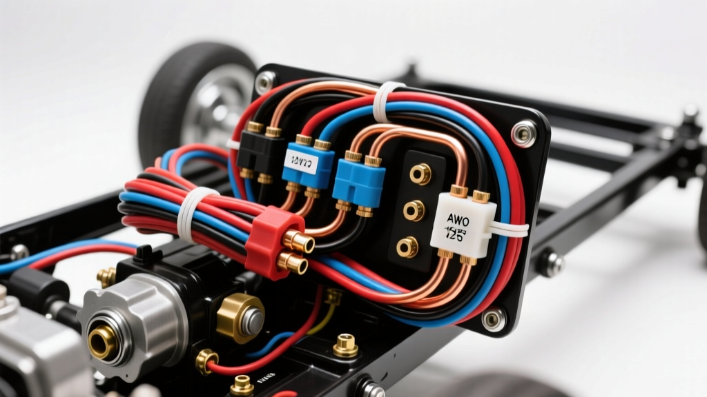
Introduction to Tri-Five Electrical Upgrades
The 1955 Chevrolet Bel Air, 150, and 210 models represent a watershed moment in American automotive design, but their original electrical systems were not built for modern accessory loads. Factory harnesses were designed for a 6-volt architecture, utilizing cloth-covered wires that are now nearly 70 years old. Upgrading to a modern 12-volt 1955 Chevy wiring harness is not just an aesthetic choice; it is a critical safety and reliability intervention. This practical how-to guide details the installation of an aftermarket 12-volt update harness (such as those from American Autowire or Painless Performance), focusing on proper routing, circuit integration, and the unique grounding requirements of the Tri-Five perimeter frame.
Pre-Installation Preparation and Safety Protocols
Before unboxing your new harness, the vehicle must be properly prepared. Disconnect the negative battery cable and remove the positive cable to eliminate any chance of a dead short while working near the bulkhead. Remove the steering column drop bracket to give yourself unobstructed access to the under-dash area. Label every original wire connected to the headlight switch, ignition switch, and wiper motor using masking tape and a fine-tip marker. Take high-resolution photographs of the original switch terminals. Once documented, carefully extract the brittle OEM harness. Inspect the firewall pass-through hole; the 1955 Chevy requires a clean, deburred hole to accommodate a heavy-duty 2.5-inch rubber firewall grommet, which is essential to prevent the sheet metal from slicing into your new wire insulation.
1955 Chevy 12-Volt Harness Circuit Specifications
When transitioning from the factory 6-volt system to a 12-volt update harness, wire gauge requirements change. Lower voltage requires thicker wires to carry the same wattage, whereas a 12-volt system allows for smaller gauge wires on most circuits. The table below outlines the standard AWG specifications and color codes for a modernized 1955 Chevy harness.
| Circuit Function | Wire Color | AWG Size | Inline Fuse Rating |
|---|---|---|---|
| Headlight Feed (to Floor Dimmer) | Red / White | 10 AWG | 20A (Circuit Breaker) |
| High Beam Headlamps | Blue | 10 AWG | N/A (On Breaker) |
| Low Beam Headlamps | Green | 10 AWG | N/A (On Breaker) |
| Taillights and Parking Lights | Brown / Yellow | 12 AWG | 15A |
| Ignition Switch (IGN / ACC) | Pink / Yellow | 12 AWG | 15A |
| Starter Solenoid Trigger | Purple | 10 AWG | N/A |
| Dash Illumination (Rheostat) | Gray / Black | 18 AWG | 5A |
| Alternator Main Charge | Red | 8 AWG | Fusible Link / 60A |
Note: Wire insulation should meet or exceed SAE J1128 Low Tension Primary Cable specifications for high-temperature automotive environments.
Step-by-Step Installation Procedure
Step 1: Firewall Pass-Through and Dash Routing
Begin by feeding the main engine bay bundle through the firewall grommet. The 1955 Chevy firewall has limited pass-through options; utilize the original master cylinder access hole or the designated passenger-side kick panel hole if your aftermarket kit includes an extended firewall branch. Apply a silicone-based wire lubricant to the grommet to prevent binding. Once inside the cabin, route the dash harness along the upper cowl support. Secure the loom every 6 to 8 inches using stainless steel loom clamps and self-tapping sheet metal screws. Avoid zip-ties near sharp metal edges, as vibration will eventually cause the plastic ties to fail and the wires to chafe against the steel dash framing.
Step 2: Headlight Switch and Floor Dimmer Integration
The 1955 Chevrolet utilizes a specific 3-position pull headlight switch with a rotary rheostat for dash lighting. Connect the main 12V battery feed (usually a 12 AWG Red wire) to the 'BAT' terminal on the switch. The tail light feed (Brown) connects to the 'TAIL' terminal. The most critical connection here is the dash illumination wire (Gray, 18 AWG), which must connect to the 'I' or 'D' terminal on the rheostat. Expert Warning: If you are installing modern LED dash gauges, do not run their high-draw backlighting through the factory headlight switch rheostat. The OEM rheostat will overheat and fail. Instead, use a dedicated relay triggered by the parking light circuit to power LED dash illumination.
Next, route the Red/White 10 AWG wire down the left-side A-pillar kick panel to the floor-mounted headlight dimmer switch. The 1955 floor dimmer features three prongs: 'B' (Battery/Power In), 'H' (High Beam Out - Blue wire), and 'L' (Low Beam Out - Green wire). Ensure the rubber boot is fully seated over the terminals to prevent moisture ingress from the floorboards.
Step 3: Ignition Switch and Alternator Upgrades
The dash-mounted ignition switch on the '55 Chevy requires precise terminal mapping. Connect the 12V constant feed (Red) to the 'BAT' terminal. The 'IGN' terminal receives the Pink wire, which powers the coil, HEI distributor (if upgraded), and wiper motor. The 'ACC' terminal (Yellow) powers the radio and accessory outlets. The 'ST' terminal must be connected to the Purple 10 AWG wire, which routes through the firewall directly to the 'S' terminal on the starter solenoid.
If you are converting from the original generator to a modern 10SI or 12SI internally regulated alternator, the original voltage regulator mounted on the radiator support must be bypassed. According to MAD Electrical 1-Wire Alternator Tech, a 1-wire alternator setup requires an 8 AWG or 10 AWG charge wire routed directly from the alternator's BAT terminal to the starter solenoid's main battery lug or the battery positive post. Do not route this charge wire back through the dash harness ammeter; the factory ammeter wiring is typically only 14 AWG and will melt under the 60+ amp load of a modern alternator. Convert the dash ammeter to a voltmeter or use a heavy-duty external shunt.
Critical Grounding Points for the 1955 Perimeter Frame
The most common cause of electrical failure in Tri-Five Chevys is inadequate grounding. The 1955 Chevy body is mounted to a perimeter frame using thick rubber body mounts. This means the body and the frame are electrically isolated from one another. You must establish heavy-duty ground straps to unify the electrical system.
- Engine Block to Frame: Use a 1/0 AWG braided copper strap from the passenger side cylinder head to the frame rail. Clean the paint off both mating surfaces to bare metal.
- Body to Frame: Install an 8 AWG braided ground strap from the body firewall or floor pan directly to the frame rail near the driver's side body mount.
- Engine Block to Firewall: Run a 4 AWG ground wire from the back of the engine block to the firewall to ensure the dash gauges and wiper motor have a clean return path.
- Headlight Buckets: The original '55 headlight buckets ground through the rust-prone radiator support. Run dedicated 14 AWG ground wires from each headlight bucket directly to the engine block or a clean frame rail ground bus.
Troubleshooting Common Tri-Five Electrical Gremlins
Even with a brand-new 1955 Chevy wiring harness, builders frequently encounter a few specific issues post-installation. Use this diagnostic tree to resolve them:
Symptom: Headlights dim severely when idling, but brighten when revving.
Cause: Voltage drop across the headlight switch or floor dimmer switch.
Fix: The factory switches were not designed for the amperage draw of modern halogen or sealed beam upgrades. Install a 30A dual-relay headlight kit. Use the factory headlight switch only to trigger the relay coils, allowing the relays to pull 12V directly from the battery to the headlamps via dedicated 10 AWG feeds.
Symptom: Turn signals hyper-flash or do not flash at all.
Cause: The original thermal flasher can (usually located clipped to the dash support) relies on the electrical resistance and heat generated by incandescent bulbs to cycle the bimetallic strip. If you have upgraded to LED taillights and front park lights, the current draw is too low to heat the strip.
Fix: Replace the thermal flasher can with an electronic LED flasher module (such as an EP35 or equivalent 3-prong electronic relay). Ensure the flasher is wired with the correct polarity if using an LED-specific module.
Symptom: The starter solenoid engages, but the engine does not crank, and dash lights go completely dead.
Cause: High resistance at the battery cable connections or a missing engine-to-chassis ground.
Fix: Verify the main 1/0 AWG battery cables are crimped (not just bolted through the strands) and that the engine block ground strap is securely fastened to bare metal. Consult the TriFive.com Technical Archives for factory ground strap locations if voltage drop persists.
Conclusion
Installing a new wiring harness in a 1955 Chevy is a meticulous process that demands patience, proper crimping tools, and a strict adherence to AWG sizing and grounding protocols. By upgrading to a modern 12-volt architecture, integrating relays for high-draw circuits, and properly isolating the body-to-frame grounds, you ensure that your Tri-Five is not only safe to drive but electrically robust enough to handle modern driving conditions and accessory loads.