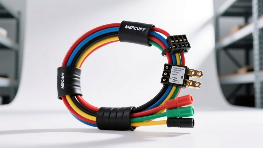
Decoding the Mercury Outboard Wiring Harness Color Code System
While automotive electrical systems share foundational principles with marine applications, the environment in which a Mercury outboard operates demands a vastly superior standard of wiring harness engineering. Saltwater, constant vibration, and high UV exposure mean that standard automotive harnesses will fail rapidly on the water. To troubleshoot, repair, or fabricate a custom harness for a Mercury or Mariner outboard, you must intimately understand the Mercury outboard wiring harness color code system and how it maps to the American Boat & Yacht Council (ABYC) E-11 standards.
This complete wiring diagram walkthrough dissects the primary harness bridging the helm station to the transom-mounted engine. We will cover ignition, starting, instrumentation, and trim circuits, providing the exact AWG specifications, pin configurations, and real-world failure modes that marine technicians face daily.
The Core Philosophy: Reading Mercury Marine Wiring Diagrams
Mercury Marine wiring diagrams are logically divided into three primary zones: the Engine Harness (internal to the cowling), the Main Harness (transom to helm), and the Helm/Instrumentation Harness. When performing a complete diagram walkthrough, the focal point is the main multi-pin connector—typically a 14-pin or 8-pin sealed AMP/Molex-style connector depending on the engine's vintage and whether it is a 2-stroke, 4-stroke, or modern EFI/DFI model.
Unlike automotive harnesses that often rely on complex multiplexed CAN-bus networks for basic gauges (though modern Mercury SmartCraft systems do use CAN), traditional Mercury outboards rely on discrete, analog wire pathways for critical functions. This makes tracing a fault with a digital multimeter (DMM) highly straightforward, provided you know the color codes.
Ignition and Starting Circuit Walkthrough
The starting and ignition circuits are the most critical pathways in the harness. A failure here leaves you stranded. Mercury utilizes a specific color palette to manage the 12V DC power distribution from the ignition switch to the engine's starter solenoid and kill circuit.
- Red (14 AWG or 10 AWG): Unswitched 12V+ battery power. This wire feeds directly from the battery or main breaker to the ignition switch 'B' (Battery) terminal, and subsequently to the engine to power the ECM/CDI and voltage regulator.
- Purple (14 AWG): Switched 12V+ ignition power. Runs from the ignition switch 'I' (Ignition) terminal to the engine. When the key is turned to 'ON', this wire energizes the fuel pump relay, ECM, and instrument gauges.
- Yellow (14 AWG): Starter solenoid trigger. Runs from the ignition switch 'S' (Start) terminal to the starter solenoid 'S' terminal. It only carries 12V while the key is held in the crank position.
- Black with Yellow Stripe (16 AWG): The Kill Circuit. This is a critical safety pathway. In older 2-stroke models, grounding this wire shorts the ignition coil primary winding, killing the spark. In modern EFI models, it signals the ECM to cut fuel and spark. It runs to the ignition switch 'M' (Magneto) terminal.
Instrumentation and Charging Circuit Walkthrough
The helm gauges require precise analog signals from the engine's stator, rectifier, and fuel tank senders. Mercury aligns closely with standard marine color codes for these instruments to ensure compatibility with aftermarket gauges like Faria or Teleflex.
- Gray (16 AWG): Tachometer signal. This wire carries the raw AC pulse from the stator or the rectified DC pulse from the tachometer terminal on the voltage regulator. The gauge interprets the frequency of this pulse to display RPM.
- Pink (16 AWG): Fuel level sender signal. Runs from the variable resistor in the fuel tank (typically 33-240 ohms or 10-180 ohms depending on the sender) to the fuel gauge 'S' terminal.
- Yellow with Black Stripe (14 AWG): Choke/Primer solenoid. Found primarily on older carbureted models, this wire activates the choke plate or enrichener valve when the ignition key is pushed in while turning.
Trim and Tilt Circuit Walkthrough
The trim and tilt system draws significant amperage (often 20 to 40 amps under load). Therefore, the control wires in the main harness are kept separate from the heavy-gauge power wires running directly to the trim pump relays.
- Blue (14 AWG): Trim Up. When the helm switch is toggled up, this wire completes the ground path for the 'Up' relay, engaging the pump in reverse polarity to raise the outboard.
- Green (14 AWG): Trim Down. Completes the ground path for the 'Down' relay, lowering the engine.
Expert Note: The actual power feeding the trim pump relays should never run through the main 14-pin helm harness. It requires dedicated 10 AWG or 8 AWG marine-tinned cables routed directly from the battery distribution block to the transom relays to prevent severe voltage drop.
Master Mercury Outboard Wire Color Code Chart
| Wire Color | Function / Circuit | Standard AWG | Destination / Terminal |
|---|---|---|---|
| Red | Main Battery 12V+ (Unswitched) | 10 or 14 | Ignition Switch 'B', ECM, Regulator |
| Purple | Switched 12V+ (Ignition ON) | 14 | Ignition Switch 'I', Gauges, Fuel Pump |
| Yellow | Starter Solenoid Trigger (Crank) | 14 | Ignition Switch 'S', Solenoid 'S' |
| Black / Yellow Stripe | Engine Kill / Magneto Ground | 16 | Ignition Switch 'M', CDI / ECM Kill |
| Gray | Tachometer Signal (Pulse) | 16 | Regulator Tach Terminal, Gauge 'SIG' |
| Pink | Fuel Tank Sender Signal | 16 | Tank Sender, Gauge 'S' |
| Blue | Trim Relay Control (Up) | 14 | Helm Trim Switch, Trim Up Relay |
| Green | Trim Relay Control (Down) | 14 | Helm Trim Switch, Trim Down Relay |
| Black | Main DC Ground / Negative | 10 or 14 | Engine Block, Battery Negative, Gauges |
Connector Pinouts and Harness Fabrication Standards
When fabricating a replacement harness or repinning a damaged connector, you must adhere to marine-grade specifications. According to SAE J1128 and ABYC E-11 standards, marine wiring must be stranded, tinned copper to resist galvanic corrosion and capillary action (where moisture wicks up the wire strands under the insulation).
The 14-Pin Main Harness Connector
Modern Mercury outboards frequently utilize a sealed 14-pin rectangular or circular connector (often an AMP Superseal or Deutsch DT equivalent) to bridge the engine and helm. When repinning this connector, always use the manufacturer-specific extraction tool to avoid damaging the silicone weather seals. If the silicone seal is compromised, salt air will corrode the brass pins within a single season, leading to high-resistance faults that mimic a failing stator or ECM.
Always pack the rear of these connectors with a high-quality, non-conductive dielectric grease (such as Mercury Perfect Seal or Nyogel 760) to displace moisture and prevent oxidation on the pin mating surfaces.
Troubleshooting Real-World Harness Failure Modes
As an electrical diagnostic technician, you will encounter specific failure patterns unique to the marine environment. Here is a diagnostic decision tree for common Mercury harness issues:
Symptom: Engine Cranks but Will Not Start (No Spark)
- Check the Kill Circuit (Black/Yellow): Disconnect the main harness at the engine. Use a DMM to check for continuity between the Black/Yellow pin and engine ground. If there is continuity with the key OFF and the harness disconnected, the wire is chafed and grounding out inside the harness sleeve, or the ignition switch 'M' terminal is internally shorted.
- Verify Switched Power (Purple): Check for 12V+ at the Purple wire pin on the engine side while the key is in the ON position. A reading below 11.5V indicates severe voltage drop, likely due to corrosion at the helm ignition switch or the main harness connector pins.
Symptom: Erratic Tachometer Readings
- Inspect the Gray Wire: The tachometer signal is highly susceptible to electromagnetic interference (EMI) and voltage drop. Ensure the Gray wire is not routed parallel to high-tension ignition leads or heavy-gauge alternator charging cables.
- Check Ground Integrity: The tachometer gauge requires a pristine ground. Perform a voltage drop test on the gauge's Black ground wire. Any reading above 0.1V under load indicates a corroded ground bus at the helm.
Symptom: Sluggish Trim and Tilt Operation
- Bypass the Helm Harness: Jump 12V+ directly to the Blue and Green wires at the transom relays. If the trim pump operates at full speed, the issue is voltage drop in the main harness or a failing helm switch.
- Measure Voltage Drop: Place your DMM in DC Volts. Put the red probe on the battery positive and the black probe on the trim relay power stud while actuating the trim. A drop greater than 0.5V dictates that the harness wire is undersized (must be minimum 10 AWG for runs over 10 feet) or heavily corroded.
Conclusion: Precision in Marine Wiring
Understanding the Mercury outboard wiring harness color code is only the first step. True mastery requires applying rigorous marine electrical standards to every repair. By utilizing tinned copper wire, respecting ABYC AWG sizing charts for long transom runs, and meticulously sealing multi-pin connectors, you ensure the vessel's electrical system remains as reliable as the engine itself. For comprehensive standards and safety guidelines, always refer to the American Boat & Yacht Council (ABYC) and official Mercury Marine Service Manuals before initiating any custom harness fabrication or major electrical overhaul.