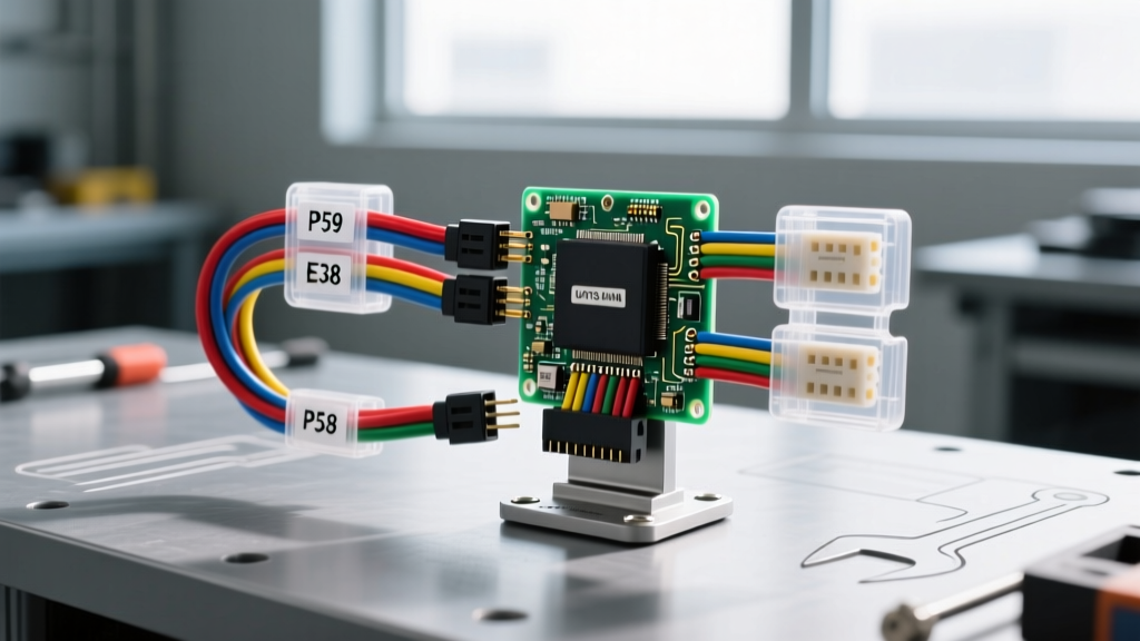
Gen III vs. Gen IV ECM Architecture and Harness Topology
Executing a flawless engine swap requires more than just mechanical mounts and fuel pressure regulators; the central nervous system—the LS wiring harness and ECU—dictates the ultimate success of the project. Whether you are running a Gen III 5.3L LM7 with a P59 ECM or stepping up to a Gen IV 6.2L LS3 with an E38 controller, understanding the distinct pinouts, ground topology, and serial data networks is non-negotiable. The transition from Gen III to Gen IV marked a massive shift in automotive electrical architecture. The Gen III P59 ECM relies on a 16-bit processor, a 1-bar MAP sensor for speed-density calculations, and Class 2 serial data for module communication. Conversely, the Gen IV E38 ECM utilizes a 32-bit processor, a native 2-bar MAP sensor, a 58x reluctor wheel topology, and a high-speed GMLAN CAN-bus network. Mating the wrong LS wiring harness and ECU combination will result in immediate communication faults, limp-mode activation, and injector synchronization failures.
P59 and E38 Power and Ground Pinout Specifications
Voltage drop is the silent killer of swapped LS engines. When fabricating or modifying an LS wiring harness, utilizing the correct AWG (American Wire Gauge) for power and ground feeds is critical. The ECU requires clean, uninterrupted voltage to properly saturate ignition coils and maintain injector dead-time compensation. Below is the critical power and ground pinout reference for the ubiquitous P59 (Gen III) and E38 (Gen IV) ECMs.
| ECM Type | Connector | Pin Number | Wire Color (OEM) | AWG Size | Function |
|---|---|---|---|---|---|
| P59 (Gen III) | C1 (Black) | Pin 1 | Orange | 10 AWG | Constant Battery + (B+) |
| P59 (Gen III) | C1 (Black) | Pin 2 | Pink | 14 AWG | Ignition 1 (Switched 12V) |
| P59 (Gen III) | C1 (Black) | Pin 57, 58 | Black | 10 AWG | Powertrain Ground |
| E38 (Gen IV) | X1 (Black) | Pin 1, 2 | Red/White | 10 AWG | Constant Battery + (B+) |
| E38 (Gen IV) | X1 (Black) | Pin 24 | Pink | 14 AWG | Ignition 1 (Switched 12V) |
| E38 (Gen IV) | X1 (Black) | Pin 73, 74 | Black/White | 10 AWG | Powertrain Ground |
Note: Always route the 10 AWG ground wires directly to the cylinder head or engine block, bypassing the chassis to prevent ground loop interference which can skew oxygen sensor readings.
VATS Bypass and Class 2 Serial Data Protocols
The Vehicle Anti-Theft System (VATS) is the most common hurdle when integrating an LS wiring harness and ECU into a non-GM chassis. Early Gen III applications utilized a resistor-based VATS system integrated into the ignition lock cylinder. However, later Gen III and all Gen IV applications rely on Class 2 serial data to verify the Body Control Module (BCM) security handshake. If the ECU does not receive the correct VATS password via the serial data line upon key-on, it will disable the fuel injectors and starter relay. While legacy methods involved splicing a 2.2k-ohm resistor into the VATS wire, the modern, reliable solution is to flash the ECU operating system. Using HP Tuners VCM Suite, tuners can navigate to the System tab and disable VATS entirely, allowing the LS wiring harness to operate independently of the donor vehicle's BCM. This is the industry standard for standalone race cars, resto-mods, and off-road swaps.
GMLAN CAN-Bus Routing and Termination
When working with Gen IV ECUs (E38, E40, E92), the LS wiring harness must accommodate the GMLAN (Global Manufacturing Local Area Network) CAN-bus. GMLAN operates at 33.3 kbps and is highly susceptible to electromagnetic interference (EMI). The CAN-High and CAN-Low wires must be routed as a twisted pair, maintaining a minimum of two twists per inch. According to SAE International standards for in-vehicle networks, the CAN-bus requires a 120-ohm terminating resistor at each end of the network bus to prevent signal reflection. When building a custom harness for an E38 swap, ensure that the OBD2 diagnostic port (Pins 6 and 14) retains the factory terminating resistors, or integrate inline 120-ohm resistors if the factory diagnostic pigtail is removed. Failure to terminate the bus will result in U0100 (Lost Communication with ECM) codes and erratic electronic throttle behavior.
Sensor Shielding and 5V Reference Topology
A deeply misunderstood aspect of the LS wiring harness is the 5-Volt Reference (5V REF) circuit. The ECU generates a highly regulated 5V signal that is shared across multiple critical sensors, including the MAP, TPS, and APPS (Accelerator Pedal Position Sensor). Because these sensors share a common 5V source and a common low-reference (ground) circuit, a short-to-ground on a single sensor wire will pull the entire 5V bus down to near zero. In a swap scenario, harness wires are often routed near exhaust headers or sharp firewall edges. If the MAP sensor 5V REF wire (typically Gray on P59, Gray/Black on E38) chafes and grounds out, the ECU will simultaneously throw P0122 (TPS Low), P0107 (MAP Low), and P2138 (APPS Correlation). To prevent this, always use shielded cable for the 5V REF and low-reference circuits when extending the harness through the firewall, and terminate the shield drain wire at the ECU connector shell, not at the sensor.
Electronic Throttle Control (ETC) Harness Integration
Gen IV LS engines utilize a Drive-by-Wire Electronic Throttle Control (ETC) system. Integrating the APPS into your custom chassis requires precise wiring to the E38 X2 (Gray) connector. The APPS uses redundant signaling for safety. You must wire the 5V Reference, Low Reference, and two distinct signal wires (Signal 1 and Signal 2) back to the ECU. Signal 1 and Signal 2 operate on inverse voltage slopes; as the pedal is depressed, Signal 1 voltage increases while Signal 2 voltage decreases. If the ECU detects a divergence between these two signals exceeding a calibrated threshold, it will immediately cut throttle power and trigger a reduced engine power (limp) mode. Ensure the APPS harness circuit is kept entirely separate from high-current circuits like the cooling fan relays or fuel pump feeds to prevent inductive voltage spikes from corrupting the analog signal.
Diagnostic Decision Tree: ECU Communication Failures
When the LS wiring harness and ECU fail to communicate with a scan tool or dash cluster, follow this structured diagnostic sequence:
- Symptom: Scan tool reads "Unable to Connect" on OBD2 port.
- Cause 1: Missing switched 12V to Pin 2 (P59) or Pin 24 (E38).
- Fix: Verify ignition relay circuit and check for blown IGN fuses.
- Cause 2: Class 2 / GMLAN serial data wire shorted to ground.
- Fix: Disconnect ECU and OBD2 port. Use a multimeter to check continuity between the serial data pin (Pin 59 on P59 C1, Pin 6 on OBD2 for GMLAN) and chassis ground. Repair short if continuity exists.
- Symptom: Engine cranks but no injector pulse; scan tool communicates.
- Cause: VATS active or missing 12V reference to injector harness.
- Fix: Verify VATS is disabled in the OS. Check the Pink/White or Pink wire at the injector sub-harness for 12V during cranking.
- Symptom: Aftermarket tachometer reads zero or erratic RPM.
- Cause: Raw LS ECU tach output is a 5V square wave, incompatible with standard 12V coil-trigger tachometers.
- Fix: Wire the Tan tach output wire (Pin 69 on P59 C2) through a 12V pull-up resistor or use a dedicated Dakota Digital SGI-5E signal interface module.
For comprehensive swap wiring diagrams and aftermarket harness integration guides, refer to the Holley Performance Technical Resource Library, which provides excellent visual references for Gen III and Gen IV connector cavities. Mastering the LS wiring harness and ECU requires patience, precision crimping (always use weather-pack or Deutsch connectors with proper ratcheting crimpers), and a thorough understanding of the underlying electrical architecture.