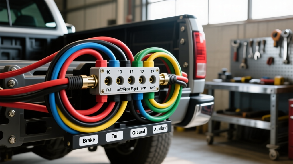
The Limitations of Factory 4-Pin Harnesses in Heavy Towing
When transitioning from light-duty utility trailers to heavy equipment haulers or travel trailers, the factory 4-pin flat connector quickly becomes a bottleneck. A standard 4-pin setup only supports tail lights, left turn/brake, and right turn/brake circuits. It completely lacks the infrastructure for electric trailer brakes, reverse lockout solenoids, and auxiliary 12V power for charging trailer breakaway batteries. Upgrading to a comprehensive 7-pin truck wiring harness for trailer applications is not just a convenience; it is a critical safety modification that ensures your brake controller can communicate effectively with the trailer's electric brakes without suffering from severe voltage drop.
Factory wiring often relies on 12 AWG or even 14 AWG wires for lighting circuits, which are routed through the vehicle's body control module (BCM) and low-amperage relays. When you plug in a 30-foot trailer with dozens of LED markers and a demanding breakaway battery, the factory harness can overheat, trigger BCM fault codes, or cause the trailer lights to flicker. This guide details the fabrication and installation of a heavy-duty, relay-isolated 7-way RV blade harness designed to handle the rigorous electrical demands of modern towing.
7-Way RV Blade Pinout and Heavy-Duty Wire Specifications
To build a reliable truck wiring harness for trailer use, you must adhere to the RVIA (Recreation Vehicle Industry Association) standard pinout for the 7-way blade connector. Using the correct wire gauge is paramount. While commercial trucks use SAE J560 (7-way round) connectors, light and medium-duty trucks utilize the 7-way RV flat blade. Below is the specification chart for a heavy-duty custom harness build.
| Pin Number | Circuit Function | Standard Wire Color | Minimum AWG Size | Protection (Fuse/Breaker) |
|---|---|---|---|---|
| 1 | Left Turn / Stop | Yellow | 10 AWG | 20A Auto-Reset |
| 2 | Reverse Lights / Lockout | Purple | 12 AWG | 15A Fuse |
| 3 | Chassis Ground | White | 8 AWG | N/A (Direct Ground) |
| 4 | Right Turn / Stop | Green | 10 AWG | 20A Auto-Reset |
| 5 | Electric Brakes Output | Blue | 10 AWG | 30A Auto-Reset |
| 6 | 12V Auxiliary Power | Red or Black | 10 AWG | 40A Auto-Reset |
| 7 | Tail / Marker Lights | Brown | 12 AWG | 15A Auto-Reset |
Wire Insulation Selection: GXL vs. Standard PVC
Do not use standard PVC-insulated wire (SAE J1128 Type GPT) for the engine bay or undercarriage routing of your truck wiring harness for trailer use. PVC becomes brittle and melts near exhaust components. Instead, source SAE J1128 compliant TXL or GXL wire. These feature cross-linked polyethylene (XLPE) insulation, which is highly resistant to abrasion, chemicals, and temperatures up to 150°C (302°F). The thin-wall construction of GXL also makes it significantly easier to pull through split-loom tubing and corrugated conduit.
Project Phase 1: Routing and Loom Protection
The physical routing of the harness dictates its long-term reliability. Begin at the rear bumper, working forward toward the engine bay and the brake controller mounting location.
- Exhaust Clearance: Maintain a minimum of 6 inches of clearance between the wiring loom and any exhaust components. If this is impossible, wrap the harness in high-temperature fiberglass sleeving or titanium exhaust wrap.
- Chassis Attachment: Use UV-resistant nylon cable ties combined with adhesive-backed mounting pads. Avoid self-tapping metal screws directly into the frame rail, as these can pierce the loom and cause dead shorts against the chassis.
- Split Loom Tubing: Encase the entire 7-wire bundle in 3/8-inch corrugated split loom tubing. Seal the ends of the tubing with electrical tape or heat-shrink end caps to prevent water ingress and capillary action from drawing moisture into the harness.
Project Phase 2: Brake Controller and Auxiliary Power Integration
The blue electric brake wire (Pin 5) and the red/black auxiliary wire (Pin 6) require dedicated high-amperage circuits. Never tap the brake controller output into the factory stoplight switch wire; this will backfeed voltage into the BCM and potentially destroy the truck's lighting control module.
Brake Controller Output Circuit
Run a dedicated 10 AWG blue GXL wire from the brake controller's output terminal under the dash, through the firewall via an existing grommet, and down the frame rail. Install a 30A Type 1 (auto-resetting) circuit breaker within 18 inches of the battery positive terminal. Type 1 breakers are essential for trailer brakes because they automatically reset once the thermal overload cools, preventing a scenario where a manual-reset breaker trips on the highway and leaves you without trailer brakes.
Upgrading the 12V Auxiliary Charge Line
Factory 12V auxiliary pins are often wired with 12 AWG wire, which suffers from massive voltage drop over a 25-foot trailer. This results in a dead breakaway battery or insufficient power for trailer living quarters. Run a dedicated 10 AWG (or even 8 AWG for trailers over 30 feet) red wire directly from the battery or alternator stud, protected by a 40A Type 1 circuit breaker. This ensures a solid 13.5V+ reaches the trailer's charge line, even under heavy alternator load.
Project Phase 3: The Critical Ground Circuit
Ninety percent of all trailer lighting and brake controller 'S.H.' (Short Circuit) errors stem from an inadequate ground. The white ground wire (Pin 3) must not rely on the trailer hitch ball for grounding. Hitch balls are coated in paint, rust, and grease, creating high electrical resistance.
- Strip 1/2 inch of insulation from the 8 AWG white wire.
- Crimp a heavy-duty, non-insulated ring terminal using a hex-compression crimper (not a standard jaw crimper).
- Locate a clean, unpainted section of the truck's steel frame rail near the rear bumper.
- Sand the area down to bare metal using 80-grit sandpaper.
- Secure the ring terminal using an M8 or M10 grade 8 bolt, a star washer (to bite through any surface oxidation), and a flange nut.
- Torque the bolt to 18-22 lb-ft and coat the terminal in dielectric grease to prevent galvanic corrosion.
Termination and Weatherproofing
When terminating the wires into the 7-way RV socket (such as a Pollak PK11893 or Hopkins Endurance connector), use adhesive-lined polyolefin heat shrink butt connectors. The adhesive lining melts and flows into the wire strands, creating a watertight seal that prevents copper oxidation. Before mating the truck plug to the trailer socket, apply a generous amount of dielectric grease (such as Permatex 22058) to the blade contacts. This prevents moisture intrusion and reduces fretting corrosion caused by highway vibrations.
Troubleshooting Voltage Drop and Ground Loops
If your trailer lights dim when the brakes are applied, or your brake controller displays a low-voltage warning, you have a voltage drop issue. According to Ohm's Law, voltage drop is calculated as V = I × R. In a 12V system, a drop of more than 0.5V on the lighting circuits or 1.0V on the brake circuit is unacceptable.
Testing Procedure: Set your digital multimeter to DC Volts. Place the black probe on the truck's battery negative terminal and the red probe on the trailer's ground pin (Pin 3) while the trailer is plugged in and the running lights are on. If you read more than 0.2V, your ground circuit has excessive resistance. Check the frame ground star washer for rust, and verify that the trailer-side ground ring terminal is equally secure to the trailer's bare steel frame. Never use self-tapping screws for grounds on aluminum or painted steel trailers; always use a bolt-and-nut through-hole connection.
Authoritative References
For further technical specifications regarding automotive primary cable and towing electrical standards, consult the following resources: