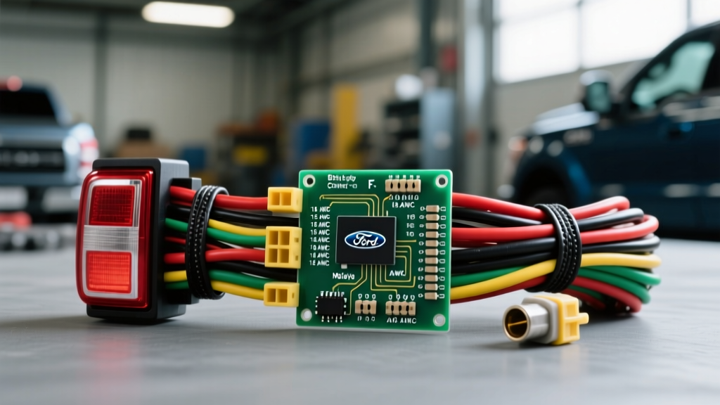
Architectural Shift: Multiplexed Lighting in the 13th-Gen F-150
When diagnosing a ford f150 tail light wiring harness on 2015–2020 (13th-generation) models, technicians must abandon legacy relay-and-fuse mental models. Ford transitioned the F-150’s exterior lighting architecture to a fully multiplexed, Body Control Module (BCM) driven system. Instead of simple 12V analog switches, the BCM utilizes solid-state field-effect transistors (FETs) and Pulse Width Modulation (PWM) to monitor circuit integrity, manage thermal loads, and execute bulb-outage detection.
This advanced technical deep dive dissects the physical routing, pinout matrix, and failure modes of the rear lighting harness. Whether you are dealing with a melted connector, a phantom BCM shutdown, or galvanic corrosion at the bed grounds, understanding the specific AWG requirements and signal behaviors is critical for a permanent repair.
OEM Connector Anatomy and Pinout Matrix
The rear lamp harness interfaces with the tail light assemblies via a 7-pin sealed connector (commonly Motorcraft pigtail WPT-1312 or WPT-1246, depending on trim and LED vs. halogen configuration). The wires are routed through the cabin, passing through a rubber grommet at the rear of the cab, and transitioning into a corrugated split-loom conduit that runs along the driver-side frame rail.
Below is the standard pinout matrix for a 2017 F-150 XLT/Lariat equipped with the standard halogen/LED hybrid tail light assembly. Always verify against your specific VIN's wiring diagram via Ford's PTS (Professional Technician System), as upfitter packages and tow-package configurations can alter the reverse and aux lighting circuits.
| Pin | Function | Wire Color (Typical) | AWG Size | BCM / SJB Reference |
|---|---|---|---|---|
| 1 | Left Stop / Turn | Yellow / Violet | 18 AWG | BCM C2280B Pin 14 |
| 2 | Tail / Marker (Run) | Brown / White | 18 AWG | BCM C2280B Pin 28 |
| 3 | Chassis Ground | Black / White | 14 AWG | G403 / G404 Bed Ground |
| 4 | Reverse Lamp Feed | White / Purple | 18 AWG | BCM C2280A Pin 42 |
| 5 | Right Stop / Turn | Green / Orange | 18 AWG | BCM C2280B Pin 15 |
| 6 | Cargo / Aux Lamp | Light Green / Brown | 18 AWG | BCM C2280C Pin 11 |
| 7 | Trailer Tow Run (If Equipped) | Brown / Light Green | 14 AWG | Tow Module C4327 |
Notice the discrepancy in wire gauges. While signal and standard bulb feeds utilize SAE J1128 compliant 18 AWG (0.8 mm²) primary cable, the ground circuit (Pin 3) and trailer tow feeds step up to 14 AWG (2.0 mm²). This is to minimize voltage drop across the extended wheelbase of the F-150, ensuring the BCM receives accurate current-sense feedback.
Critical Failure Modes: Beyond the Blown Fuse
Because the BCM utilizes internal solid-state relays, you will rarely find a traditional blown mini-fuse for a tail light circuit on a 13th-gen F-150. Instead, the BCM monitors current draw and voltage drop. If it detects a short to ground, an open circuit, or excessive resistance, it triggers a Fault Protection Mode, shutting down the specific FET and logging a Diagnostic Trouble Code (DTC) such as B116C (Left Stop Lamp Circuit Open) or B116D (Right Stop Lamp Circuit Short to Ground).
Failure Mode 1: Galvanic Corrosion at Bed Grounds (G403/G404)
The 13th-gen F-150 features an aluminum-alloy body and bed, but the harness ground ring terminals are often tinned copper or steel, secured with zinc-plated steel bolts. When the factory dielectric barrier is compromised by road salt, moisture, and dissimilar metals, severe galvanic corrosion occurs. This introduces high resistance into the 14 AWG ground wire. The BCM interprets this voltage drop as a short or overload and shuts down the tail light circuit entirely. Symptoms include flickering tail lights, hyper-flashing turn signals, or complete illumination failure without any blown fuses.
Failure Mode 2: Connector Fretting and Tin Oxidation
The 7-pin rear lamp connectors are exposed to high-frequency vibration from the bed and rear suspension. Over time, micro-movements cause fretting corrosion between the male and female terminals. If the terminals are tin-plated rather than silver-plated, tin oxide builds up, creating a diode-like effect that restricts current flow. This is particularly devastating to the PWM signals used for LED tail light arrays, causing the BCM to falsely detect a "bulb out" condition.
Failure Mode 3: Harness Chafing at the Bed Rail
On models equipped with the max tow package or aftermarket bed liners, the main harness branch routing from the cab grommet to the rear crossmember is prone to chafing against the steel frame rail. The corrugated loom degrades under UV and thermal cycling, allowing the 18 AWG Brown/White (Tail) wire to short against the frame, instantly triggering BCM fault protection.
Advanced Diagnostics: Oscilloscope and Voltage Drop Protocols
Using a standard Digital Multimeter (DMM) or a test light to diagnose a BCM-controlled ford f150 tail light wiring harness will often lead to misdiagnosis. A test light draws current, which the BCM may interpret as a short, immediately shutting down the circuit. A DMM averages the PWM signal, often displaying a confusing 7.5V or 9.2V reading instead of a clean 12V.
Step-by-Step Diagnostic Tree
- Visual & Physical Inspection: Disconnect the 7-pin connector at the tail light. Inspect the cavity for moisture ingress. Use a magnifying loupe to check the female terminals for spread pins or green/white tin oxide buildup.
- Voltage Drop Testing (Ground Side): With the tail lights commanded ON via the headlight switch, set your DMM to DC Volts. Place the red probe on the battery negative post and the black probe on Pin 3 (Black/White) at the tail light connector. A reading greater than 0.10V indicates unacceptable resistance in the ground path, necessitating ground ring terminal replacement and bed bolt cleaning.
- Oscilloscope Signal Tracing: Back-probe Pin 1 (Left Stop/Turn) with a PicoScope or equivalent automotive oscilloscope. When the brake is applied, you should see a clean 12V square wave if the BCM is performing a bulb-check PWM sequence, followed by a solid 13.5V (alternator voltage) DC line. If the signal drops to 0V after 500 milliseconds, the BCM has detected an anomaly and entered fault protection.
- BCM Reset Procedure: If the BCM has latched a hard fault, repairing the harness will not immediately restore power. You must clear the DTCs using a bi-directional scan tool (e.g., Ford FDRS or Autel MaxiSys) or perform a hard reset by disconnecting the negative battery cable and the BCM backup battery (if equipped) for 15 minutes to discharge the capacitor banks.
Harness Repair Protocol: Pigtails, Crimps, and Sealing
When repairing a compromised section of the tail light harness, "T-taps" and twist-on solder connectors are strictly prohibited. They introduce resistance, fail under automotive vibration, and violate OEM electrical repair standards. Follow this protocol for a factory-grade repair:
1. Wire Stripping and Preparation
Use a precision wire stripper calibrated for 18 AWG and 14 AWG. Do not nick the copper strands, as this reduces the cross-sectional area and creates a stress-riser that will snap under vibration. Strip exactly 6mm (1/4 inch) of insulation.
2. Terminal Crimping and Splicing
For inline harness repairs, use sealed butt splices with an integrated adhesive-lined heat shrink. If replacing the connector, source an OEM Motorcraft pigtail (e.g., WPT-1312). Use a ratcheting open-barrel crimp tool (such as the TE Connectivity or Hozan P-707) to crimp the terminals. A proper crimp will exhibit a distinct "wing" formation and pass a pull-test of at least 15 lbs for 18 AWG wire.
3. Environmental Sealing
Seal all inline splices using Raychem RW-200 or 3M dual-wall heat shrink tubing with a 3:1 shrink ratio. The inner polyamide adhesive layer must melt and extrude slightly from the ends of the tubing to ensure a watertight seal against road brine. For the connector cavity, pack the rear wire-entry seals with Nyogel 760G or a high-quality dielectric grease to prevent moisture wicking into the harness capillary action.
4. Ground Terminal Restoration
If G403/G404 is corroded, cut off the old ring terminal and crimp a new 14 AWG sealed ring terminal. Clean the aluminum bed grounding surface with a brass wire brush (never steel, which embeds particles and accelerates galvanic corrosion). Secure the ground using a new OEM flange bolt. Torque to the factory specification (typically 76 Nm / 56 lb-ft for M8 bed bolts). Coat the exterior of the ground joint with a dedicated anti-corrosion compound, ensuring no grease is trapped between the ring terminal and the aluminum mating surface.
Summary
The ford f150 tail light wiring harness is a highly engineered, multiplexed network that demands precision diagnostics and strict adherence to OEM repair methodologies. By understanding the BCM's fault-protection logic, respecting the specific AWG requirements, and mitigating galvanic corrosion at the bed grounds, technicians can permanently resolve rear lighting faults and restore the vehicle's safety systems to factory specifications.