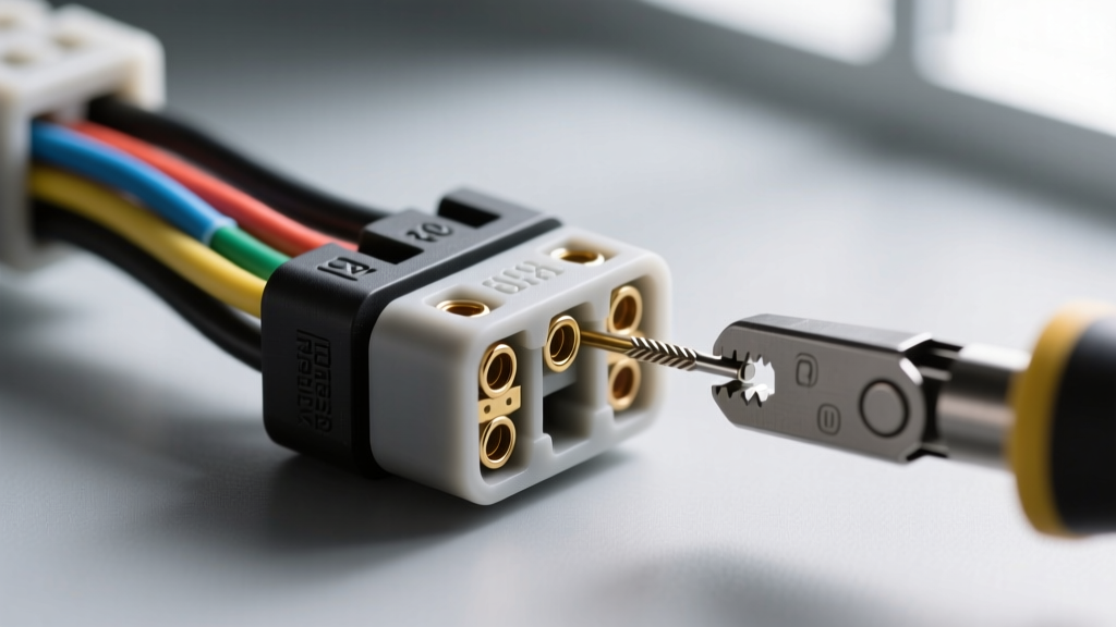
Engineering the Interface: Automotive Wiring Harness Connector Pins
When fabricating custom engine swap harnesses or repairing OEM electrical systems, the integrity of the circuit is ultimately dictated by the wiring harness connector pins. The plastic housing merely provides environmental sealing and alignment; the actual electrical and mechanical joint occurs at the terminal interface. In high-vibration automotive environments, a poorly crimped or improperly seated pin will lead to voltage drops, intermittent sensor faults, and potentially catastrophic thermal events. This advanced technical deep dive explores the metallurgy, crimp geometry, retention mechanics, and precision extraction protocols required for high-reliability automotive terminations, referencing USCAR and SAE standards.
Base Metallurgy and Contact Plating
Automotive connector pins are predominantly stamped from copper alloys to balance electrical conductivity with the mechanical spring properties required for the primary locking lance. The two most common base metals are C26000 (cartridge brass) for cost-effective, high-volume applications, and C51000 (phosphor bronze), which offers superior stress relaxation resistance for high-temperature underhood environments.
The contact plating dictates the terminal's current-carrying capacity and corrosion resistance:
- Tin (Sn): Standard for low-to-medium current circuits (e.g., 18 AWG Pink switched ignition feeds or 16 AWG Black grounds). Tin requires higher mating normal force (typically 3-5 Newtons) to break through the native tin oxide layer during insertion.
- Silver (Ag): Utilized for high-amperage circuits such as alternator outputs, starter solenoids, and EV power distribution. Silver maintains excellent conductivity at elevated temperatures but is susceptible to sulfur-induced tarnishing if the secondary environmental seal fails.
- Gold (Au): Flash-plated (typically 100 micro-inches) over a nickel underplate for low-current, high-reliability data and sensor circuits. Gold is essential for 18 AWG Dark Green (CAN-High) and CAN-Low networks, as well as low-level analog signals from MAF and O2 sensors, because it does not oxidize and requires minimal mating force (under 1 Newton).
Crimp Geometry: The F-Crimp and I-Crimp Interface
The transition from the circular cross-section of the wire to the flat stamping of the terminal pin is governed by strict geometric tolerances. A proper crimp consists of two distinct zones: the conductor crimp (F-crimp) and the insulation crimp (I-crimp).
Bellmouth and Conductor Brush Specifications
According to USCAR-21 standards, the F-crimp must exhibit specific geometric features to ensure optimal tensile strength and electrical conductivity without severing the copper strands:
- Front Bellmouth: A small flare at the front of the conductor crimp (typically 0.25mm to 0.75mm) that prevents the sharp edge of the terminal stamping from cutting into the wire strands during flexing.
- Rear Bellmouth: A critical flare at the rear of the conductor crimp (minimum 0.5mm to 1.0mm). The absence of a rear bellmouth acts as a stress concentrator, leading to copper fatigue and strand breakage under engine vibration.
- Conductor Brush: The wire strands must protrude slightly past the front of the conductor crimp (0.5mm to 1.5mm) to verify full insertion depth before the crimp tool cycles.
- Insulation Crimp (I-Crimp): Must securely grip the wire jacket without piercing it. For 16 AWG TXL wire, the I-crimp should support a minimum deflection of 45 degrees without the wire pulling out of the insulation barrel.
USCAR-21 Mechanical and Electrical Specifications
When selecting wiring harness connector pins for a custom LS swap harness or repairing a factory Delphi/Aptiv harness, matching the terminal series to the wire gauge and expected current load is non-negotiable. The following table outlines standard pull-out forces and current ratings for common automotive terminal families.
| Terminal Series | Wire Range (AWG / mm²) | Max Current Rating | Min. Pull-Out Force (Newtons) | Primary Application |
|---|---|---|---|---|
| Metri-Pack 150 | 22-18 AWG (0.35-0.80) | 14 Amps | 45 N (10.1 lbs) | Injectors, Sensors, ECU I/O |
| Metri-Pack 280 | 18-12 AWG (0.80-3.00) | 30 Amps | 70 N (15.7 lbs) | Ignition Coils, Fan Relays |
| AMP Superseal 1.5 | 20-14 AWG (0.50-2.00) | 14 Amps (1.5mm pin) | 50 N (11.2 lbs) | ABS Modules, TCM Connectors |
| Deutsch DT (Size 16) | 18-14 AWG (0.80-2.00) | 13 Amps | 67 N (15.0 lbs) | Off-road, Marine, Swaps |
| Weather-Pack (Male/Female) | 16-12 AWG (1.50-3.00) | 20 Amps | 60 N (13.5 lbs) | Legacy GM, Lighting, Horns |
Primary Locks and Terminal Position Assurance (TPA)
Modern wiring harness connector pins rely on a dual-locking system to prevent 'push-out'—a failure mode where the mating force of the opposing terminal pushes the pin backward out of the housing cavity. The primary lock is the flexible metal lance stamped directly into the terminal body. When inserted into the plastic housing, the lance snaps over a molded plastic shoulder, producing an audible and tactile 'click'.
However, under high mating forces (common in 40+ pin ECU connectors), the primary lance can deflect backward. To counteract this, secondary locks known as Terminal Position Assurances (TPAs) or Comb Retainers are employed. The TPA is a rigid plastic insert that slides into the housing after all pins are seated. If a pin is not fully inserted, the TPA will physically jam against the terminal shoulder, preventing full closure and alerting the technician to a mis-seated pin before the harness is plugged into the PCM.
Precision Extraction: Avoiding Housing and Tang Damage
Extracting wiring harness connector pins without destroying the delicate primary lance or gouging the plastic housing cavity requires specialized extraction tools and precise technique. Using improvised tools like sewing needles or paperclips often bends the lance permanently, resulting in a terminal that will no longer lock into the housing.
- Select the Correct Tool: For Delphi Metri-Pack 280 terminals, use the Delphi 12094428 (or equivalent J-38125) extraction tool. For Weather-Pack, use the ribbed tubular extractor that fits precisely over the terminal barrel.
- Disengage the TPA: If the connector utilizes a secondary lock, use a small flat-blade screwdriver to gently pry the TPA back into its 'pre-lock' or 'unlocked' position. Never force a pin out while the TPA is fully engaged.
- Align and Insert the Tool: Slide the extraction tool over the wire and into the front (mating side) of the connector cavity. The tool must be perfectly square to the housing to avoid wedging against the plastic cavity wall.
- Depress the Lance: Push the tool inward until you feel it bottom out against the terminal shoulder. This action mechanically collapses the primary locking tang away from the plastic locking ramp.
- Extract from the Rear: While maintaining forward pressure on the extraction tool to keep the tang depressed, gently pull the wire from the rear (wire side) of the connector. Never pull the extraction tool itself to remove the pin; the tool is only meant to depress the lock.
- Inspect the Lance: Once removed, inspect the terminal's primary lock. If the tang is bent flat against the terminal body, it must be carefully picked back up to its original 45-degree angle using a fine scribe, or the terminal must be discarded and replaced.
Real-World Failure Modes in Swaps and Custom Harnesses
When performing complex engine swaps, such as integrating a Gen III LS harness into a classic chassis, technicians often encounter specific failure modes related to terminal misapplication:
- Fretting Corrosion: Occurs when gold-plated ECU pins are mated with tin-plated aftermarket pigtail terminals. The micro-movements caused by engine vibration wear away the gold flash, exposing the dissimilar metals to moisture and creating a high-resistance galvanic cell. Always match plating materials across the mating interface.
- Thermal Hotspots from Under-Crimping: If the crimp tool die is worn or set too wide for an 18 AWG wire, the resulting loose F-crimp will exhibit high millivolt drop. Under continuous loads (e.g., electric cooling fan relays), this resistance generates localized heat, melting the PVC/TXL insulation and eventually causing a short to ground.
- Seal Plug Omission: In sealed connector systems like the AMP Superseal or Metri-Pack, a silicone ribbed seal must be slipped over the wire before crimping. If a cavity is left empty in a multi-pin connector, a silicone cavity plug must be inserted to maintain the environmental seal. Omitting these plugs allows capillary action to wick moisture down the wire jacket and directly into the ECU.
Authoritative References
For further engineering data on terminal crimp profiles and automotive electrical standards, consult the following resources:
- SAE J1128: Low Tension Primary Cable - Society of Automotive Engineers (Insulation and conductor specifications for automotive wire).
- USCAR-21: Electrical Terminal Crimp Requirements - United States Council for Automotive Research (Definitive guide on crimp geometry, bellmouth, and pull-out testing).
- TE Connectivity Automotive Application Tooling - Manufacturer specifications for AMP and Superseal crimp die sets and extraction protocols.