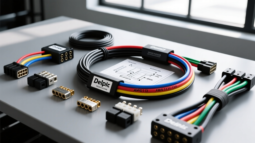
The Reality of PSI Wiring Harness Instructions in Modern LS/LT Swaps
When executing a complex GM LS or LT engine swap, relying on generic, out-of-the-box documentation is a recipe for electrical gremlins. Standard PSI wiring harness instructions provided by aftermarket manufacturers offer a baseline for basic connectivity, but they frequently gloss over the nuanced integration required for modern chassis merging, CAN-bus termination, and high-current fuel pump architectures. As automotive electrical systems have evolved from simple 12V switched circuits to sophisticated multiplexed networks, your installation methodology must evolve accordingly.
This advanced technical deep dive bypasses the rudimentary 'connect red to red' advice. Instead, we focus on the critical integration points of a PSI (Performance Systems Integration) conversion harness, specifically targeting E38 and E92 ECM platforms, Delphi connector integrity, and high-amperage peripheral management.
Phase 1: Harness Audit and Delphi Connector Verification
Before the harness ever touches the engine bay, a meticulous bench audit is mandatory. Aftermarket harnesses are often assembled in high-volume environments where terminal seating can be compromised. The PSI harness relies heavily on Delphi (now Aptiv) Metri-Pack and Weather-Pack connector families.
Metri-Pack 150 vs. 280 Series Terminal Checks
- Metri-Pack 150 Series (Sensors & 5V Ref): Used for low-current circuits like the MAP sensor, TPS, and coolant temperature. These terminals handle up to 14 amps but are typically carrying less than 1 amp. Verify that the 18 AWG wires exhibit a proper bell-crimp and that the secondary TPA (Terminal Position Assurance) lock is fully seated. A backed-out 5V reference pin on the ECM will cascade a failure across all shared 5V sensors.
- Metri-Pack 280 Series (Injectors & Ignition): Used for medium-current loads. The PSI harness routes injector drivers and ignition coil triggers through these robust connectors. Ensure the 14 AWG or 16 AWG wires are not experiencing 'wire pull-out' and that the silicone weather seals are not pinched, which would compromise the IP67 waterproof rating.
According to SAE J1113 standards for Electromagnetic Compatibility, improper crimping or exposed wire strands at the connector rear can act as an antenna, injecting EMI (Electromagnetic Interference) directly into the ECM's sensitive logic boards. Always use dual-wall, adhesive-lined heat shrink over any repaired or extended harness legs.
Phase 2: Chassis Integration and Firewall Bulkhead Routing
The most common failure point in any swap harness is the firewall pass-through. Standard PSI wiring harness instructions usually suggest drilling a new hole and using a generic rubber grommet. This is unacceptable for modern swaps where the OBD2 diagnostic port and CAN-bus lines must pass into the cabin.
- Identify the OEM Bulkhead Location: Whenever possible, reuse the donor vehicle's factory firewall grommet. If modifying an older chassis (e.g., a 1969 Camaro), use a stepped, marine-grade bulkhead connector rather than a simple rubber pass-through to prevent chafing against the sheet metal.
- Separate High and Low Current: Route the 10 AWG main power feeds (Orange) and ground circuits (Black) on one side of the firewall, and the low-voltage OBD2/CAN-bus lines on the other. This physical separation prevents inductive coupling from high-amperage fuel pump or cooling fan circuits from corrupting the CAN High/Low data signals.
- Drip Loops: Form a drip loop on the engine side of the firewall before the harness enters the grommet. Gravity will pull moisture down the harness jacket; the loop ensures water drips off before reaching the cabin seal.
Critical PSI Harness Pinout & AWG Reference Chart
When merging the PSI harness with your chassis fuse block or standalone relay panel, reference this critical circuit table. These specifications apply to standard Gen IV (E38) and Gen V (E92) ECM integrations.
| Circuit Function | Wire Color (PSI Standard) | AWG Size | ECM Connector / Pin | Notes & Integration Rules |
|---|---|---|---|---|
| Main ECM Ignition | Pink | 12 AWG | X1 / Pin 1 | Must be switched 12V. Do not share with fuel pump relay coil. |
| Main ECM Battery | Orange | 10 AWG | X2 / Pin 1 | Constant 12V. Requires dedicated 30A Maxi fuse at battery. |
| ECM Power Ground | Black/White | 10 AWG | X2 / Pin 73 | Must ground directly to engine block, NOT chassis or cylinder head. |
| Fuel Pump Relay Control | Dark Green | 18 AWG | X2 / Pin 8 | Low-side driver. Connects to Bosch relay Pin 85. Pin 86 to switched 12V. |
| CAN-Bus High (OBD2) | Dark Green/White | 20 AWG | X1 / Pin 50 | OBD2 Pin 6. Requires 120-ohm termination resistor if isolated. |
| CAN-Bus Low (OBD2) | Dark Blue/White | 20 AWG | X1 / Pin 51 | OBD2 Pin 14. Keep twisted pair intact; max 2 twists per inch. |
| Tachometer Output | Tan/White | 18 AWG | X1 / Pin 42 | Provides a 5V square wave pulse. May require a filter for analog gauges. |
Phase 3: Fuel Pump and Cooling Fan Relay Architecture
Many installers misinterpret the fuel pump circuit in aftermarket PSI wiring harness instructions. The E38/E92 ECM does not output 12V to run the fuel pump; it provides a switched ground (low-side driver) to trigger a relay. Furthermore, modern LT engines utilize a PWM (Pulse Width Modulated) Fuel Pump Control Module (FPCM) to regulate fuel pressure dynamically based on engine load.
Bypassing the Factory PWM Fuel Pump Module
If you are dropping an LT1 or LT4 into a classic chassis and opting for a standard return-style fuel system with a fixed-pressure regulator (e.g., Aeromotive 58 PSI), you must bypass the PWM module and reprogram the ECM.
- Relay Selection: Use a heavy-duty, sealed 40A Bosch-style relay. Standard 30A automotive relays will suffer from contact arcing and voltage drop under the continuous 15-20A draw of a Walbro 450 or Deatschwerks DW400 pump.
- Wiring the Relay: Connect ECM Pin X2-8 (Dark Green) to Relay Pin 85. Connect Relay Pin 86 to a clean, switched 12V ignition source. Run a dedicated 8 AWG power feed directly from the battery (via a 40A ANL fuse) to Relay Pin 30. Connect Relay Pin 87 to the fuel pump positive terminal using 10 AWG wire.
- ECM Calibration: You must use HP Tuners or similar software to disable the FPCM diagnostic codes (P064A, P064B) and set the fuel pump duty cycle to a fixed 100% output in the ECM calibration tables.
Advanced Troubleshooting: When the Engine Cranks but Won't Fire
When following advanced PSI wiring harness instructions, if the engine cranks but fails to start, avoid randomly probing wires. Use this systematic decision tree to isolate the electrical fault.
Symptom 1: No Injector Pulse, No Spark, but 500+ RPM on Scanner
- Cause: ECM is not seeing a valid crankshaft position signal, or the VATS (Vehicle Anti-Theft System) is active.
- Fix (Crank Signal): Verify the 12V feed to the crank sensor (Pin A, usually Pink). Check the 58x reluctor wheel alignment. If using a 24x reluctor on an E38 ECM, the harness pinout must be repinned at the ECM connector to match the Gen III configuration, or the ECM must be flashed for 24x operation.
- Fix (VATS): Connect an OBD2 scanner. If U-codes or P1682 (Ignition 1 Switch Circuit 2) are present, the ECM is immobilized. Use HP Tuners to disable VATS in the 'System' or 'Anti-Theft' tabs.
Symptom 2: Intermittent Stalling or Random Misfires Under Load
- Cause: Poor ECM grounding or EMI interference on the injector driver circuits.
- Fix: The ECM grounds (X1-73, X2-73, X3-73) must be terminated to a bare metal surface on the engine block. Remove all paint, powder coat, and primer. Use a star washer and torque to 10 lb-ft. As noted in GM Upfitter Guidelines, relying on the cylinder head or chassis for ECM logic grounds introduces variable resistance that corrupts injector pulse-width calculations under high alternator output.
Symptom 3: OBD2 Scanner Will Not Communicate
- Cause: CAN-bus termination failure or swapped High/Low pins at the OBD2 port.
- Fix: Measure the resistance between OBD2 Pin 6 (CAN High) and Pin 14 (CAN Low) with the key off and battery disconnected. You should read exactly 60 ohms. If you read 120 ohms, you are missing a termination resistor in the harness. If you read 0 ohms, the CAN lines are shorted together, likely due to a crushed harness at the firewall bulkhead. Refer to SAE J1979 OBD-II standards for precise diagnostic link connector (DLC) pinout mandates.
Final Integration Checklist
Before applying battery power for the first time, perform a continuity check on all main power and ground circuits. Verify that the 10 AWG Orange battery feeds show infinite resistance to ground (preventing a dead short upon initial power-up). Ensure all Delphi connectors 'click' audibly and that the secondary TPA locks are engaged. By treating your PSI wiring harness not just as a plug-and-play accessory, but as a critical, high-speed data and power distribution network, you guarantee a reliable, professional-grade LS/LT swap that starts on the first key turn and idles flawlessly.