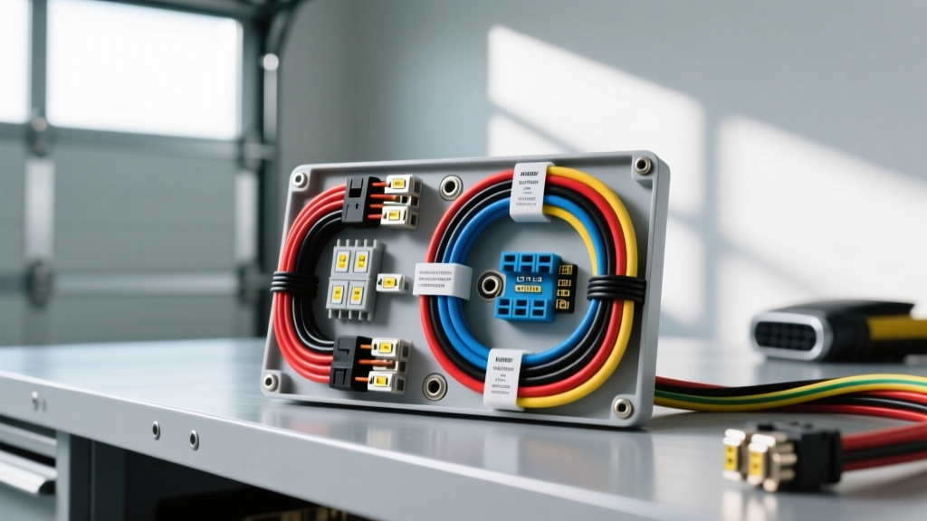
The Hidden Dangers of Improper DRL Harness Integration
Integrating a custom or replacement daytime running lights wiring harness is one of the most common electrical modifications in automotive builds. According to the National Highway Traffic Safety Administration (NHTSA), DRLs significantly reduce daytime multi-party crashes by increasing vehicle conspicuity. However, from an electrical engineering perspective, splicing into factory headlight circuits without understanding current loads, multiplexed networks, and thermal limits can lead to catastrophic harness fires, melted bulkhead connectors, and destroyed Body Control Modules (BCMs).
This guide details the most severe mistakes made when installing aftermarket or OEM-replacement DRL harnesses, providing the exact specifications, wire gauges, and diagnostic procedures required to execute the job safely.
Mistake #1: Bypassing the Relay for High-Current Halogen DRLs
The most frequent and dangerous error occurs when installers wire high-draw halogen DRL bulbs (such as 9005 or H11) directly through the factory headlight switch or a low-amperage ignition trigger. A standard 9005 halogen bulb draws approximately 5.0 Amps at 12.8V. When a DRL harness powers two of these in parallel, the total continuous current draw exceeds 10 Amps.
Many OEM headlight switch connectors and clock-spring ribbons are only rated for 2 to 3 Amps, as they are designed to send a low-current signal to a BCM or relay, not to carry the primary headlight load. Bypassing a relay will rapidly overheat the 18 AWG or 20 AWG factory signal wires, melting the plastic connector housing and causing a dead short.
The Safe Solution: ISO Mini Relay Integration
Always use a standard ISO 4-pin mini relay (Bosch-style) to isolate the high-current load from the trigger circuit. According to Littelfuse automotive relay specifications, a standard 30A/40A ISO mini relay safely handles the inrush current of cold halogen filaments.
- Pin 85 (Trigger): Connect to the ignition or DRL trigger signal using 18 AWG wire.
- Pin 86 (Ground): Connect to a clean chassis ground using 18 AWG wire.
- Pin 30 (Power In): Connect directly to the battery positive terminal via a dedicated 15A inline fuse using 12 AWG wire.
- Pin 87 (Load Out): Connect to the DRL lamp positive feeds using 12 AWG wire.
Mistake #2: Ignoring PWM and Series-Wired DRL Circuits
On many General Motors platforms (particularly the GMT800 Silverado/Sierra and Tahoe/Yukon from 1999–2006), the factory DRL system does not supply a standard 12V constant signal. Instead, the OEM DRL module wires the high-beam bulbs in series to operate them at 6V, reducing brightness and extending filament life. Furthermore, the module uses Pulse Width Modulation (PWM) to dim the DRLs when the parking lights are engaged.
Splicing a standard 12V aftermarket daytime running lights wiring harness into this series circuit will force 12V through bulbs designed for 6V operation in that specific state, instantly blowing the filaments. Worse, backfeeding 12V into the OEM DRL module's control pins (typically Pin C1-10 on the GM DRL module) will fry the internal solid-state switching transistors, requiring a costly module replacement.
Diagnostic Fix for GM Series DRLs
If retaining OEM series operation, your replacement harness must match the factory pinout and utilize dual-contact relays to switch the bulbs from series (DRL mode) to parallel (High Beam mode). If bypassing the OEM system entirely, you must physically cut and cap the series feed wires at the headlight pigtails to prevent backfeeding, and rewire the DRLs in parallel with a dedicated 12V relay harness.
Mistake #3: Tapping CAN-Bus and Multiplexed BCM Networks
In modern vehicles (2015 and newer), lighting circuits are rarely simple 12V switched feeds. They are controlled by a Body Control Module (BCM) utilizing LIN (Local Interconnect Network) or CAN-bus protocols, often employing PWM to monitor circuit integrity and detect bulb outages.
Tapping a DRL harness trigger wire directly into a CAN-bus wake-up line or a multiplexed headlight feed without proper isolation will introduce parasitic capacitance and voltage spikes into the network. This frequently triggers U-codes (e.g., U0140 - Lost Communication with BCM) and forces the vehicle into a fail-safe lighting mode.
Safety Protocol: Opto-Isolation
Never hard-splice a DRL trigger into a multiplexed network. Instead, use an opto-isolator module or a CAN-bus-safe LED decoder harness. These devices read the voltage state or PWM signal optically, triggering the DRL relay via an isolated internal circuit without electrically bridging the vehicle's data network to the aftermarket harness.
DRL Wiring Harness Safety Audit & Specification Table
Use the following specification chart to ensure your daytime running lights wiring harness meets automotive electrical safety standards. Wire gauges are based on standard copper stranded wire with a 12.8V nominal system voltage.
| Circuit Function | Minimum AWG | Standard Color Code | Protection / Fuse | Connector Type |
|---|---|---|---|---|
| Battery Feed (Relay Pin 30) | 12 AWG (or 10 AWG for long runs) | Red | 15A ATO/ATC Blade Fuse | Ring Terminal (Battery Post) |
| DRL Load Feed (Relay Pin 87) | 14 AWG (Halogen) / 18 AWG (LED) | Blue or Yellow | Protected by Pin 30 Fuse | Weather-Pack / Metri-Pack |
| Ignition/DRL Trigger Signal | 18 AWG | White or Light Green | 5A Mini Fuse (if tapped at source) | Posi-Tap or OEM T-Harness |
| Chassis Ground (Relay Pin 86) | 16 AWG | Black | N/A | Ring Terminal w/ Star Washer |
| Parking Light Override (Kill) | 18 AWG | Brown | N/A (Signal Only) | Solder & Heat Shrink |
Mistake #4: Inadequate Grounding and Ghost Voltage Backfeeding
A DRL harness is only as reliable as its ground. A common mistake is securing the harness ground ring terminal to a painted chassis bolt or a sheet metal bracket that flexes. This creates a high-resistance ground path.
When the ground resistance increases, the current seeks an alternative path to ground, often backfeeding through the high-beam or low-beam filament ground circuits. This results in "ghost voltage," where the instrument cluster illumination dims when the DRLs activate, or the ABS warning light flickers due to voltage bleeding into the CAN-bus ground reference.
The Proper Grounding Procedure
- Locate a factory grounding stud or a thick, structural chassis component (not thin sheet metal).
- Remove the bolt and use a wire brush or sandpaper to strip the paint and e-coat down to bare, shiny metal.
- Install the harness ground ring terminal, followed by a star washer to bite into the metal and prevent vibration loosening.
- Coat the terminal with dielectric grease or anti-corrosion compound to prevent galvanic corrosion.
- Perform a voltage drop test across the ground circuit with the DRLs active. A reading above 0.10V indicates excessive resistance.
Thermal Routing and Insulation Standards
Engine bays generate extreme heat, and routing a daytime running lights wiring harness too close to exhaust manifolds or turbocharger downpipes is a severe fire hazard. Standard primary automotive wire is governed by the SAE J1128 Low Tension Primary Cable Standard, which typically rates standard cross-linked polyethylene (XLPE) insulation up to 125°C. However, radiant heat from exhaust components can easily exceed 150°C, causing the insulation to melt and short against the chassis.
Safety Warning: Maintain a minimum clearance of 6 inches from exhaust components. If routing near the engine block or headers is unavoidable, the harness must be sleeved in Tefzel (PTFE) tubing or high-temperature fiberglass silicone sleeving, and secured using stainless steel P-clips rather than nylon zip ties, which will become brittle and fail under thermal cycling.
Troubleshooting Decision Tree: DRL Harness Failures
Use this diagnostic tree to identify and resolve common post-installation DRL harness issues:
- Symptom: DRLs remain on when headlights or parking lights are turned on.
- Cause: Missing or improperly wired parking light override circuit.
- Fix: Wire a standard 12V diode (e.g., 1N4004) with the band facing the DRL trigger relay. Tap the diode's anode into the factory parking light positive feed. When parking lights energize, the 12V reverse-biases the diode, cutting the trigger signal to the DRL relay.
- Symptom: DRLs flicker rapidly or strobe when the engine is running.
- Cause: Alternator AC ripple voltage leaking into the DRL trigger circuit, or tapping into a factory PWM-dimmed circuit.
- Fix: Install a 1000µF electrolytic capacitor across the relay trigger pins (85 and 86) to smooth the voltage ripple, or relocate the trigger source to a clean ignition-switched 12V fuse in the cabin fuse block.
- Symptom: LED DRLs cause hyper-flashing turn signals or bulb-outage warnings on the dash.
- Cause: The BCM detects a low-current draw on the shared circuit and assumes a bulb is burnt out.
- Fix: Install 50W 6-Ohm load resistors on the affected circuits, ensuring they are mounted to bare metal chassis to dissipate heat safely.
By adhering to these electrical standards and avoiding common integration shortcuts, your daytime running lights wiring harness will provide reliable, safe, and legal illumination for the life of the vehicle.