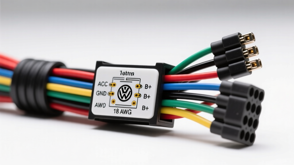
Understanding VW Jetta Radio Harness Architecture
When upgrading, diagnosing, or replacing the head unit in a Volkswagen Jetta, decoding the Jetta factory wiring harness color codes is the most critical step in the installation process. Volkswagen transitioned its infotainment architecture significantly between the Mk4 (1999–2005) and Mk5/Mk6/Mk7 (2005–Present) generations. While older Mk4 models utilized a standard dual 8-pin ISO connector, modern Jettas rely on the complex 54-pin TE Connectivity Quadlock (T54) connector. This VW radio wiring diagram reference provides the exact pinouts, wire color codes, and AWG specifications required for seamless OEM replacement or aftermarket adapter integration.
Unlike traditional automotive electrical systems that rely on a switched 12V ignition wire to wake the radio, modern VW infotainment units utilize a Controller Area Network (CAN-bus) wake signal. Misinterpreting the Jetta factory wiring harness color codes—specifically the CAN-High and CAN-Low circuits—is the leading cause of parasitic battery drain and Comfort Control Module (CCM) faults in modified vehicles.
Quadlock (T54) Connector Pinout Specifications
The Quadlock connector is divided into four distinct blocks: Block A (Power and Speakers), Block B (Data and CAN-bus), Block C (Auxiliary/Video), and Block D (Antenna). Below is the definitive reference for Block A and Block B, which handle the primary electrical and data routing for the head unit.
Block A: Power, Ground, and Speaker Outputs
Block A houses the heavy-gauge power delivery wires and the low-gauge speaker outputs. According to SAE J1128 Low Tension Primary Cable Standards, the power circuits in this block require high-strand-count copper to minimize voltage drop under peak amplifier draw.
| Pin | Function | Wire Color | AWG | Notes |
|---|---|---|---|---|
| 12 | Chassis Ground | Brown | 12 AWG | Must be terminated to a clean chassis point if extending. |
| 15 | +12V Constant Battery | Red / White Stripe | 14 AWG | Direct from Terminal 30 (Battery Positive). |
| 16 | +12V Ignition (Mk4/Early) | Red / Yellow Stripe | 16 AWG | Often unused in CAN-bus Mk5+ models; radio wakes via CAN. |
| 1 | Front Left Speaker (+) | Purple / White | 18 AWG | Phase critical for DSP/Fader operation. |
| 2 | Front Left Speaker (-) | Purple / Brown | 18 AWG | Do not ground; VW uses BTL (Bridge-Tied Load) amps. |
| 3 | Front Right Speaker (+) | Blue / White | 18 AWG | Phase critical for DSP/Fader operation. |
| 4 | Front Right Speaker (-) | Blue / Brown | 18 AWG | Do not ground; VW uses BTL (Bridge-Tied Load) amps. |
| 5 | Rear Left Speaker (+) | Green / White | 18 AWG | Rear deck or door mounted depending on trim. |
| 6 | Rear Left Speaker (-) | Green / Brown | 18 AWG | Do not ground to chassis. |
| 7 | Rear Right Speaker (+) | White / Blue | 18 AWG | Rear deck or door mounted depending on trim. |
| 8 | Rear Right Speaker (-) | White / Brown | 18 AWG | Do not ground to chassis. |
Block B: CAN-Bus and Data Communication
Block B is the nerve center for the infotainment system. It interfaces directly with the vehicle's CAN-bus gateway. When consulting a VW radio wiring diagram for aftermarket harness adapters (such as PAC AAI-VW or iDatalink Maestro), these are the wires that must be accurately tapped or emulated.
| Pin | Function | Wire Color | AWG | Notes |
|---|---|---|---|---|
| 4 | CAN-Low (Infotainment) | Orange / Green | 20 AWG | Twisted pair with CAN-High. Do not separate the twist. |
| 5 | CAN-High (Infotainment) | Orange / Brown | 20 AWG | Twisted pair. Carries the 'Wake' and 'Sleep' commands. |
| 9 | Telephone Mute / GALA | Gray / Blue | 22 AWG | Speed-dependent volume signal (GALA) on older harnesses. |
| 10 | K-Line (Diagnostics) | Gray / White | 22 AWG | Used for VCDS/OBD2 diagnostic polling of the radio. |
Antenna Amplifier and Phantom Power Requirements
A frequently overlooked aspect of the Jetta factory wiring harness is the antenna circuit. Volkswagen utilizes a Fakra Z-type coaxial connector for the AM/FM antenna. Unlike traditional passive whip antennas, the Jetta's rear-window diversity antenna features an integrated low-noise amplifier (LNA). This LNA requires 12V 'phantom power' sent directly up the center conductor of the coaxial cable from the head unit.
If your aftermarket radio does not output 12V phantom power on the antenna lead, or if you fail to install an inline phantom power adapter (e.g., Metra 40-VW10), you will experience severe signal attenuation, resulting in static and an inability to pull in local FM stations. The power wire for the antenna amplifier adapter must be spliced into Pin 16 (Red/Yellow) or an ignition-switched 12V source from the adapter harness to ensure the amplifier powers down when the vehicle is parked.
Wire Gauge, Crimping, and Terminal Extraction Specs
When repairing or extending the VW Jetta radio harness, adhering to TE Connectivity Automotive Harness Specifications is mandatory to prevent terminal push-out and arcing. The Quadlock T54 connector uses specific micro-timer and MQS (Micro Quadlok System) terminals.
- Wire Stripping Length: For 18 AWG speaker wires, strip exactly 5.5mm to 6.0mm of insulation. Exposing more than 6.5mm risks a short circuit inside the dense Quadlock housing.
- Crimp Profile: Use a ratcheting crimp tool calibrated for MQS terminals. The crimp must achieve a minimum pull-out force of 30 Newtons for 18 AWG wire.
- Terminal Extraction: Never use a standard pick to remove a pin from a T54 connector. You must use the VW T10007 (or equivalent TE 1571289-1) extraction tool to depress the primary and secondary locking lances simultaneously without damaging the plastic housing.
Troubleshooting Common Jetta Radio Harness Failures
Even with a perfect VW radio wiring diagram, real-world installations often present unique electrical faults. Use this diagnostic decision tree to resolve common issues:
Symptom: Vehicle Battery Drains Overnight After Radio Swap
- Cause: The aftermarket radio or CAN-bus interface is failing to send the 'Sleep' command to the CAN-bus gateway, or the radio's constant 12V wire is backfeeding the ignition circuit.
- Fix: Verify that the CAN-High (Orange/Brown) and CAN-Low (Orange/Green) wires are spliced using solder and heat shrink, maintaining the factory twist rate (at least 1 twist per inch). Ensure the aftermarket interface module is configured via DIP switches or firmware to recognize the specific Jetta model year to properly broadcast the CAN sleep frame.
Symptom: Radio Turns On, But No Audio from Speakers
- Cause: The vehicle is equipped with the factory Fender Premium Audio or Dynaudio external amplifier. The head unit outputs low-level pre-out signals, not speaker-level signals, and the external amp requires a CAN-bus wake signal to turn on.
- Fix: You cannot use a standard speaker-level wiring harness adapter. You must install a CAN-bus integration module (like the Maestro RR or PAC AudioPRO) that translates the Quadlock digital wake signal into a 12V remote turn-on lead for your aftermarket amplifier, while routing the RCA pre-outs correctly.
Symptom: Intermittent Loss of Steering Wheel Controls (SWC)
- Cause: High resistance on the LIN-bus (Local Interconnect Network) or degraded ground at the clock spring.
- Fix: Steering wheel controls on Mk6/Mk7 Jettas do not use discrete resistor ladder wires; they use a single-wire LIN-bus data line. Verify the LIN-bus wire (typically Purple/White or Green/Yellow depending on the exact steering column module) is securely seated in Block C of the Quadlock. Use a digital multimeter to verify a steady 12V square wave on the LIN line when buttons are pressed.
Authoritative References
For advanced diagnostics, factory scan tool procedures, and module coding, technicians should consult the following resources:
- VW ErWin (Electronic Repair and Workshop Information) - The official portal for OEM wiring schematics, TSBs, and connector cavity views.
- SAE J1128 Low Tension Primary Cable Standard - Governs the insulation thickness, temperature ratings, and AWG specifications for automotive primary wire.
- TE Connectivity Automotive Harness Specifications - Manufacturer data sheets for the MQS and Quadlock terminal crimp profiles and insertion forces.