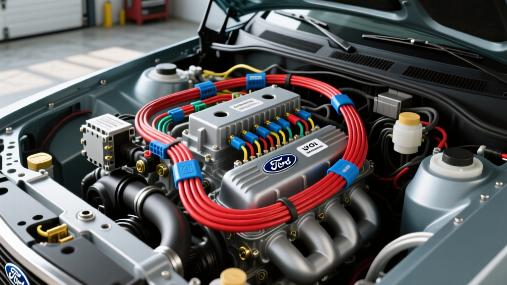
Understanding the 7.3L Powerstroke Electrical Architecture
The Ford 7.3L Powerstroke (1994.5–2003) utilizes a Hydraulic Electronic Unit Injector (HEUI) system that demands a highly specialized electrical architecture. Unlike common rail diesels, the 7.3L relies on an Injector Driver Module (IDM) to step up the vehicle's 12V DC battery voltage to a 115V DC square wave. This high-voltage pulse is required to actuate the injector solenoids, which in turn allow high-pressure engine oil to fire the fuel into the cylinders. Because of this extreme voltage and the harsh under-hood environment, the factory engine harness is prone to specific failure modes. Utilizing an accurate 7.3 wiring harness diagram is the first step in executing a comprehensive reliability upgrade and modification project.
Decoding the 7.3 Wiring Harness Diagram: Main to UVCH
The engine wiring harness on the 7.3L is split into two primary sections: the main engine harness (which routes from the IDM and PCM through the engine valley) and the Under Valve Cover Harnesses (UVCH). The main harness is notorious for chafing against the driver's side valve cover bracket and the transmission dipstick tube, leading to short circuits that can instantly destroy the IDM. The UVCH, meanwhile, suffers from thermal degradation and connector pin fretting due to engine vibration.
UVCH 9-Pin Connector Pinout & Wire Specifications
Each cylinder bank utilizes a 9-pin rectangular connector to pass through the valve cover gasket. Below is the definitive pinout and wire gauge specification for the UVCH interface. When fabricating a custom harness or repairing a melted connector, you must adhere to SAE J1128 standards for low-tension primary cable, while using high-temperature insulation rated for under-valve-cover conditions.
| Pin | Function | Typical Wire Color | AWG Size | Voltage / Current |
|---|---|---|---|---|
| 1 | Injector 1 Signal | White/Red | 18 AWG | 115V DC Peak |
| 2 | Injector 2 Signal | White/Blue | 18 AWG | 115V DC Peak |
| 3 | Injector 3 Signal | White/Green | 18 AWG | 115V DC Peak |
| 4 | Injector 4 Signal | White/Yellow | 18 AWG | 115V DC Peak |
| 5 | Injector Common (Return) | Red/Black | 16 AWG | 115V DC Common |
| 6 | Glow Plug 1 | Yellow/Black | 10 AWG | 12V / 110A |
| 7 | Glow Plug 2 | Yellow/Black | 10 AWG | 12V / 110A |
| 8 | Glow Plug 3 | Yellow/Black | 10 AWG | 12V / 110A |
| 9 | Glow Plug 4 | Yellow/Black | 10 AWG | 12V / 110A |
Upgrade Project 1: The UVCH & Connector Retention Mod
The factory 9-pin connectors are notorious for vibrating loose, causing open circuits on the injector solenoids (triggering DTC P1293 or P1294). Furthermore, the internal harness wires often break right at the crimp terminals due to the extreme thermal cycling inside the valve cover. For this modification project, we recommend replacing the internal UVCH with an upgraded PTFE (Teflon) insulated harness and performing the famous "50-Cent Mod" to ensure permanent connector retention.
Step-by-Step UVCH Upgrade Procedure
- Valve Cover Removal: Disconnect the batteries. Remove the 8mm valve cover bolts. Warning: These are M6x1.0 bolts threading into aluminum. Do not use an impact gun, or you will strip the cylinder head threads.
- Extract the Old Harness: Unclip the 9-pin connector from the valve cover gasket. Push the harness inward and carefully pull it through the gasket seal to avoid tearing the silicone.
- Install the PTFE Harness: Route the new high-temp UVCH through the gasket. Connect the internal injector and glow plug spade terminals. Ensure the locking tabs on the spades are fully engaged; a loose spade will arc and melt the internal connector.
- The Connector Retention Mod: The factory plastic retaining clip on the external side of the valve cover often becomes brittle and snaps. To prevent the external harness from vibrating out of the 9-pin socket, place a US Quarter (or a precisely cut 0.060-inch thick stainless steel shim) between the connector housing and the retaining clip before bolting it down. This applies constant outward pressure on the terminals, eliminating micro-arcing.
Upgrade Project 2: Main Engine Harness Chafe Prevention
A thorough review of the 7.3 wiring harness diagram reveals that the main harness must navigate a tight path from the IDM (mounted on the driver's side inner fender) across the engine valley to the passenger side, and then down to the transmission. The most critical failure point is where the harness rests against the driver's side valve cover bracket and the aluminum transmission dipstick tube guide. Over 100,000 miles, engine torque roll wears through the factory corrugated split loom, exposing the 115V injector wires. If a 115V wire shorts to the engine block, it will feed high voltage directly back into the IDM, frying the internal capacitors and MOSFETs.
Executing the Main Harness Loom Upgrade
- Inspection: Carefully unwrap the factory split loom from the IDM connector back to the passenger side valve cover. Inspect the insulation for micro-abrasions. Wrap any exposed copper in liquid electrical tape.
- Sleeving Installation: Slide a 1/2-inch PET (Polyethylene Terephthalate) expandable braided sleeving over the entire length of the main engine harness. PET sleeving is rated for continuous use at 125°C and offers superior abrasion resistance compared to standard nylon. For extreme heat areas near the turbocharger pedestal, use SAE J20 compliant fiberglass/silicone sleeving.
- Securing the Loom: Do not use standard vinyl electrical tape, which will melt and leave a corrosive adhesive residue. Instead, use self-fusing high-temperature silicone tape to secure the ends of the PET sleeving. Use UV-resistant nylon cable ties to secure the harness away from the dipstick tube, ensuring a minimum 1/2-inch clearance from any sharp aluminum casting edges.
Diagnostic Testing & Ohm Specifications
After completing your harness upgrades, you must verify circuit integrity before reassembly. Using a high-quality digital multimeter, test the circuits directly at the IDM harness connector (with the IDM disconnected and the key OFF).
| Circuit Tested | Expected Resistance (Ohms) | Failure Mode Indication |
|---|---|---|
| Injector Solenoid (Common to Signal) | 2.0 Ω to 5.0 Ω | Open circuit (>10kΩ) indicates broken UVCH wire or failed solenoid. |
| Glow Plug Circuit (Harness to Ground) | 0.1 Ω to 2.0 Ω | High resistance indicates corroded spade terminal under valve cover. |
| Injector Signal to Engine Block (Ground) | OL (Over Limit / Infinite) | Any resistance reading indicates a short to ground in the main harness. |
Reassembly Torque Specifications
Proper torque is critical when reassembling the 7.3L top end. Over-torquing the valve cover bolts will snap the M6 bolts or crack the cast aluminum valve cover ears, leading to massive oil leaks that will quickly degrade your newly installed UVCH.
| Component | Fastener Size | Torque Specification |
|---|---|---|
| Valve Cover Bolts | M6 x 1.0 (8mm Head) | 89 in-lbs (10 Nm) |
| IDM Mounting Bracket | M8 x 1.25 | 18 ft-lbs (24 Nm) |
| Injector Hold-Down Bolts | M6 x 1.0 | 89 in-lbs (10 Nm) |
Authoritative References & Further Reading
When modifying high-voltage diesel injection circuits, always cross-reference your work with established engineering standards and OEM documentation. For detailed OEM wiring schematics and diagnostic flowcharts, consult the official Motorcraft Service manuals specific to your model year. Adhering to SAE standards for wire gauge and thermal insulation ensures your custom 7.3 wiring harness modifications will survive the extreme demands of the HEUI injection system for hundreds of thousands of miles.