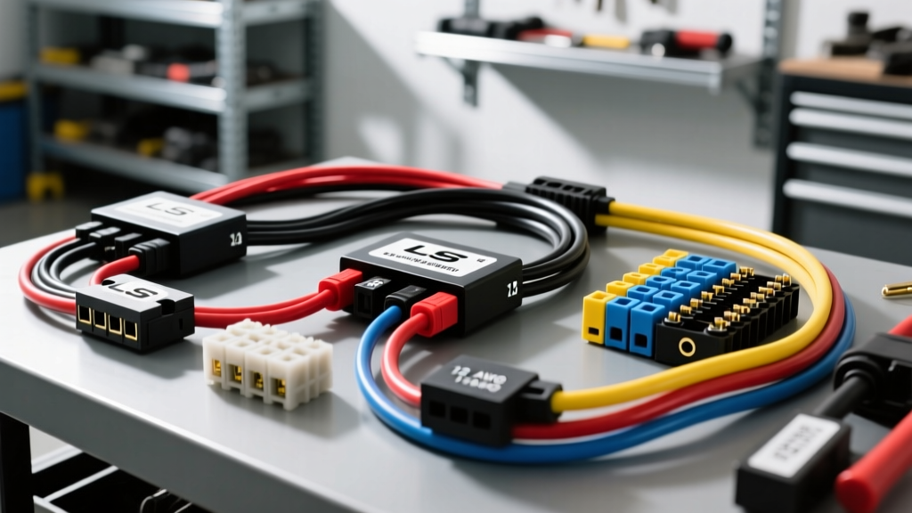
The Reality of 'Plug and Play' Engine Harnesses
In the aftermarket automotive electrical world, the term 'plug and play wiring harness' is frequently misunderstood. While a high-quality standalone harness eliminates the tedious process of crimping individual sensor pigtails and mapping injector circuits, it does not mean you can simply drape the wires over the engine and turn the key. A true plug-and-play installation for a GM LS-series engine swap still demands meticulous routing, strict adherence to AWG current limits, and precise bulkhead pass-through procedures. This guide details the professional installation of a standalone plug and play wiring harness designed for LS swaps utilizing popular ECUs like the Holley Terminator X or GM E38 controllers.
Phase 1: Pre-Installation Prep & Loom Verification
Before routing the harness into the engine bay, uncoil it on a clean, flat surface. Inspect the loom material. Most premium harnesses use split-loom tubing or braided PET sleeving. If your harness uses split-loom, secure it with high-temperature electrical tape (such as Tesa 51036) every 8 inches. Never use standard vinyl electrical tape under the hood, as the adhesive will melt and create a corrosive residue on the wire jackets.
Verifying Terminal Crimps
Inspect the ECU connectors (typically Delphi Metri-Pack 280 series for main power and GT150 series for sensors). Perform a 'pin drag test' using a spare male terminal. If the terminal slides in without a distinct click and mechanical resistance, the receptacle tang is bent. Use a precision pick to carefully lift the locking tang. Additionally, verify that the core crimps exhibit a proper 'bellmouth'—a tiny flare of wire strands just past the insulation grip—which ensures the wire will not pull out under vibration, a critical requirement outlined in the SAE J1128 Low-Tension Cable Standard.
Phase 2: Engine Bay Routing & Firewall Pass-Through
Routing dictates the longevity of your harness. The golden rule of automotive wiring is maintaining a minimum 6-inch clearance from all exhaust manifolds and headers. If this is physically impossible due to tight engine bays, you must wrap the affected harness section in titanium exhaust wrap or use a silicone-coated fiberglass firesleeve.
Firewall Bulkhead Integration
Your plug and play wiring harness will feature a main cabin pass-through grommet. Measure the outer diameter of the grommet and drill the firewall accordingly. Use a step-drill bit to ensure a perfectly round hole, preventing sharp metal edges from slicing into the wire jackets. Lubricate the grommet with pure silicone grease (never petroleum-based Vaseline, which degrades EPDM rubber) before pulling the cabin-side connectors through. Secure the grommet to the firewall using stainless steel self-tapping screws, ensuring no wires are pinched behind the flange.
Phase 3: Power Feeds & Critical Grounding Specifications
The most common cause of ECU failure and erratic sensor readings in LS swaps is inadequate grounding. A plug and play harness relies on the vehicle's chassis and engine block to complete the high-current circuits. You must establish a dedicated ground strap between the engine block and the chassis.
| Circuit Type | Required AWG | Wire Color (Standard) | Termination & Hardware |
|---|---|---|---|
| Main ECU Battery Feed | 10 AWG | Red | 3/8' Ring Terminal to Distribution Block |
| Ignition Switched 12V | 12 AWG | Pink | Fused (15A) to IGN Run/Start Source |
| Engine Block to Chassis | 4 AWG (Min) | Bare / Black Jacket | M10 Bolt to bare metal, star washer |
| Alternator Sense Wire | 14 AWG | Red / White Tracer | Fused (10A) directly to Battery (+) |
| Fuel Pump Relay Feed | 10 AWG | Gray | 30A Relay to Fuel Pump Module |
Executing the Ground Connection
Locate the dedicated ground bosses on the rear of the LS cylinder heads (typically M8 or M10 threaded holes). Remove any paint, powder coating, or rust from the mating surface using a wire wheel or sanding disc. Attach the harness ground ring terminal using a Grade 8 or stainless steel bolt. Torque to 15 lb-ft. Once torqued, coat the exterior of the connection with dielectric grease to prevent galvanic corrosion. Never place dielectric grease between the mating surfaces, as it is an insulator and will cause voltage drops.
Phase 4: Dash Integration & ECU Pinouts
While the engine-side sensors are truly plug-and-play, integrating the ECU with your vehicle's dashboard gauges requires splicing into the harness's 'dash output' pigtail. Refer to the Holley Terminator X Main Harness Manual or your specific ECU documentation for exact pinouts. Below is a standard reference for integrating common LS ECU outputs to aftermarket gauge clusters (like Dakota Digital or AutoMeter).
| Function | Typical Wire Color | Signal Type | Connection Notes |
|---|---|---|---|
| Tachometer Output | White | 5V Square Wave | Connect to gauge 'Tach' input; may require pull-up resistor |
| Speedometer Output | Green | 4000 PPM (Typical) | Verify VSS pulses per mile in ECU software |
| Check Engine Light (MIL) | Brown | Ground Trigger | Connects to negative side of dash indicator bulb |
| Coolant Temp Sender | Yellow/Black | Variable Resistance | Do NOT splice to ECT sensor; use dedicated dash sender |
| Alternator Excite | Green/White | 12V Switched | Required to 'wake up' 1-wire and 3-wire alternators |
Phase 5: Alternator & Accessory Wiring
Many LS swap plug and play wiring harness kits include provisions for the alternator. If you are using a GM CS130D or AD244 alternator, the harness will feature a 4-pin connector. Only pins 'L' (Lamp/Excite) and 'S' (Sense) are typically used. The 'S' pin must be wired directly to the battery positive terminal or main distribution block via a fused 14 AWG wire to ensure accurate voltage regulation. Routing the sense wire to the alternator's own output post will cause the system to overcharge as it attempts to compensate for voltage drop across the main charge wire.
Troubleshooting Common 'Plug and Play' Failures
Even with a premium harness, installation errors can mimic component failures. Use this decision tree to diagnose common post-installation issues:
- Engine Cranks but No Spark/Injector Pulse: Check the main ECU power relay. Ensure the 12V switched ignition wire (Pink) is receiving a minimum of 11.5V during the 'Start' position of the key cylinder. Many older ignition switches drop voltage significantly during cranking.
- Erratic TPS or MAP Sensor Readings: This is almost always a 5V reference ground issue. Verify the sensor ground wire (usually Black or Black/White tracer) has continuity to the ECU ground pin, not just the engine block. Sensor grounds must return directly to the ECU to prevent 'dirty' ground loops.
- Alternator Not Charging: Verify the alternator excite wire is receiving 12V when the key is in the 'Run' position. If using a 1-wire alternator, ensure the main charge cable is a minimum of 4 AWG and routed directly to the battery or starter solenoid, bypassing any undersized factory ammeter shunts.
For further technical validation on wire gauge ampacity and thermal degradation limits in high-heat engine bays, consult the Painless Performance LS Wiring Guide. By treating your plug and play wiring harness with the same precision as a fully custom-built loom, you ensure reliable, noise-free operation for your LS swap, whether it is destined for the drag strip or daily highway commuting.