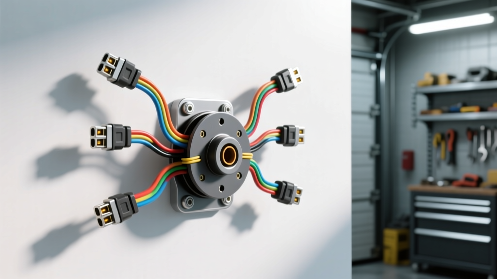
Introduction to 7-Way Trailer Brake Wiring Harness Diagnostics
A properly functioning trailer brake wiring harness is the single most critical safety link between your tow vehicle and your trailer. When electric brakes fail, pulse erratically, or lock up unexpectedly, the root cause almost always traces back to a fault within the harness, the connector, or the grounding path. The industry standard for heavy-duty towing is the 7-way RV blade connector, governed by the SAE J286 Standard. This standard dictates the physical pin layout, but real-world degradation, improper splicing, and voltage drop frequently compromise the system.
This guide provides a systematic, step-by-step troubleshooting flow for diagnosing faults in a trailer brake wiring harness. We will cover multimeter testing, AWG wire specifications, brake magnet resistance calculations, and ground path verification. Grab your digital multimeter (DMM) and follow this diagnostic sequence from the tow vehicle receptacle to the trailer brake magnets.
Phase 1: The 7-Way RV Blade Pinout and Wire Specification Chart
Before testing, you must understand the standard wiring architecture. The electric brake circuit relies on Pin 2, which must be fed by 10 AWG wire to handle the amperage required by multiple brake magnets without suffering catastrophic voltage drop over a 25-foot trailer length.
| Pin | Function | Standard Wire Color | Minimum AWG | Max Ampacity / Notes |
|---|---|---|---|---|
| 1 | Ground (Chassis) | White | 10 AWG (8 AWG preferred) | Must bond directly to trailer frame |
| 2 | Electric Brakes | Blue | 10 AWG | 12V DC from brake controller (up to 12A+) |
| 3 | Tail / Running Lights | Brown | 12 AWG | 15A fuse typical |
| 4 | 12V Auxiliary Power | Black | 10 AWG | Charges trailer breakaway battery |
| 5 | Right Turn / Stop | Green | 12 AWG | 20A fuse typical |
| 6 | Left Turn / Stop | Yellow | 12 AWG | 20A fuse typical |
| 7 | Backup / Reverse Lights | Purple | 12 AWG | Often used for reverse lockout solenoids |
Phase 2: Tow Vehicle Receptacle Voltage & Signal Testing
The first step in our troubleshooting flow is to verify that the tow vehicle is outputting the correct signal. Do not test the trailer until the vehicle side is proven functional.
- Set your DMM to DC Volts (20V scale).
- Verify the Ground Reference: Place the black probe on Pin 1 (Ground) and the red probe on Pin 4 (12V Auxiliary). With the ignition ON, you should read between 13.2V and 14.4V. If you read 0V or erratic voltage, your tow vehicle's ground or auxiliary fuse is blown.
- Test the Brake Output (Pin 2): Move the red probe to Pin 2 (Blue / Electric Brakes). Have an assistant press the manual override slider on your cabin brake controller fully to the left. You should see a solid 12V to 14V reading. If the voltage pulses, your controller is in proportional mode and is reacting to vehicle deceleration; switch the controller to manual boost or test while parked to get a static reading.
- Load Testing: If voltage at Pin 2 reads correctly (13V+) but drops below 10V when the trailer is connected, you have a high-resistance fault inside the 7-way plug, typically caused by splayed brass pins or internal corrosion.
Phase 3: Trailer-Side Harness & Ground Path Verification
According to the etrailer Wiring FAQ and master technicians, 80% of all trailer brake wiring harness failures are not shorts or broken wires, but inadequate grounding. The hitch ball is not a reliable ground path due to paint, grease, and articulation movement.
- Inspect the White Wire (Pin 1): Trace the white wire from the trailer-side 7-way plug. It must terminate at a clean, bare-metal point on the main trailer chassis tongue.
- Terminal Hardware Check: The ground must be secured using a 10 AWG or 8 AWG ring terminal, fastened with a stainless steel bolt, a flat washer, and a star washer to bite through surface rust and paint. Apply dielectric grease over the completed connection to prevent galvanic corrosion, but never inside the terminal-to-metal contact area.
- Ground Voltage Drop Test: With the trailer connected and brakes applied manually, place one DMM probe on the tow vehicle's negative battery terminal and the other on the trailer's main chassis tongue. A reading above 0.5V indicates a failing ground bond.
Phase 4: Breakaway System and Magnet Wiring Diagnostics
If the harness and ground are verified, the next node in our troubleshooting flow is the breakaway switch and the brake magnets themselves. The breakaway switch is a Normally Closed (NC) circuit. When the lanyard pin is inserted, the circuit is open. When pulled, 12V from the breakaway battery flows directly into the blue brake wire, bypassing the tow vehicle.
Testing Brake Magnet Resistance (Ohms)
A standard 12V electric brake magnet draws approximately 3.0 to 3.5 amps. Using Ohm's Law (R = V / I), a single healthy magnet should measure between 3.4 and 4.0 ohms. Because trailer brake magnets are wired in parallel, the total resistance drops as you add more axles.
- Single Axle (2 Magnets): Expected DMM reading: 1.7 to 2.0 ohms.
- Tandem Axle (4 Magnets): Expected DMM reading: 0.85 to 1.0 ohms.
- Triple Axle (6 Magnets): Expected DMM reading: 0.56 to 0.66 ohms.
To test, disconnect the blue brake wire at the trailer's main junction box or axle splice. Set your DMM to Ohms (Ω). Place one probe on the disconnected blue wire harness and the other on the white ground wire. Compare your reading to the chart above. If the DMM reads 'OL' (Open Loop), you have a severed blue wire or a blown inline splice. If it reads '0.0' or near zero, the blue wire is shorted to the chassis ground.
Step-by-Step Troubleshooting Decision Tree
Use this diagnostic decision tree to isolate the exact failure point in your trailer brake wiring harness based on the symptoms presented at the brake controller display or on the road.
Symptom A: Brake Controller Displays 'S.H.' or 'Short'
- Cause: The blue brake wire is making contact with the trailer chassis or the white ground wire before reaching the magnets.
- Diagnostic Step: Inspect the 7-way plug for melted plastic bridging Pin 1 and Pin 2. Inspect the area where the harness passes through the trailer frame grommets. Look for pinch points near the axle U-bolts.
- Fix: Repair the chafed insulation using adhesive-lined marine-grade heat shrink. Replace the 7-way plug if internal pins are bridged.
Symptom B: Brakes Lock Up When Headlights Are Turned On
- Cause: Cross-talk or a short between the Brown (Running Lights) wire and the Blue (Brakes) wire. This is a classic symptom of a melted trailer junction box or corroded trailer tail light housing backfeeding into the brake circuit.
- Diagnostic Step: Disconnect the trailer harness. Turn on the tow vehicle headlights. Test Pin 2 on the trailer plug with a DMM. If 12V is present on the blue wire with only the headlights on, the short is inside the trailer harness.
- Fix: Open the trailer side marker lights and tail lights. Check for corroded sockets where the brown and blue wires terminate. Clean or replace the junction box.
Symptom C: Controller Displays 'O.L.', 'N.C.', or No Output
- Cause: Open circuit. The brake controller cannot 'see' the electrical load of the brake magnets.
- Diagnostic Step: Perform the Phase 4 Ohms test. If the resistance is infinite, trace the blue wire from the 7-way plug to the first axle splice. Check the breakaway switch; if the internal contacts are corroded or the switch is stuck in the 'open' position, it will break the circuit to the axles.
- Fix: Replace the breakaway switch. If the switch is functional, repair the severed blue wire using a solder-seal butt connector (never use standard crimp connectors under a trailer chassis, as moisture ingress will cause rapid copper oxidation).
Symptom D: Brakes Feel Weak or Pulse Erratically
- Cause: Severe voltage drop due to undersized wiring or a failing ground path. The Tekonsha Troubleshooting Guide frequently cites inadequate 10 AWG grounding as the culprit for erratic proportional controller behavior.
- Diagnostic Step: Measure voltage at the brake magnet wire *at the wheel hub* while the controller is applying maximum manual power. If the voltage at the hub is less than 10.5V (while the battery reads 13.5V), you have a voltage drop exceeding 20%.
- Fix: Upgrade the main trunk of the trailer brake wiring harness from 12 AWG to 10 AWG. Re-terminate the white ground wire using a star washer and bare metal prep.
Conclusion
Troubleshooting a trailer brake wiring harness requires moving past simple visual inspections and utilizing a multimeter to verify voltage, resistance, and ground integrity. By following this step-by-step flow—starting at the SAE J286 7-way receptacle, verifying the ground path, and calculating parallel magnet resistance—you can accurately diagnose and permanently repair harness faults, ensuring safe and reliable towing performance.