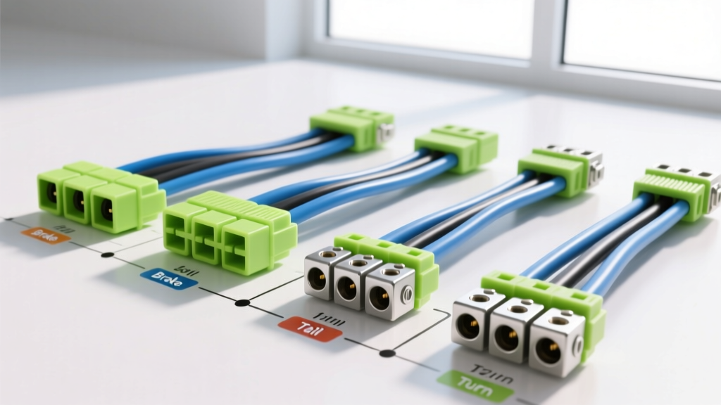
Introduction to SAE Trailer Wiring Standards
Understanding the correct wiring harness trailer diagram is critical for safe towing, legal compliance, and preventing electrical damage to both the tow vehicle and the trailer. The Society of Automotive Engineers (SAE) establishes the baseline for these configurations under standard SAE J286, which dictates the physical dimensions, pin assignments, and circuit functions for trailer connectors. Furthermore, the wire used in these harnesses must comply with SAE J1128 specifications for low-tension automotive primary cable, ensuring resistance to heat, moisture, and chemical degradation.
Modern tow vehicles often utilize multiplexed CAN-bus lighting systems and pulse-width modulation (PWM) for taillights. Connecting a standard trailer harness directly to these systems without a powered isolation module can trigger dashboard fault codes or damage the vehicle's body control module (BCM). This technical reference provides exact pinouts, wire color codes, and American Wire Gauge (AWG) requirements for the most common trailer harness configurations.
4-Way Flat Connector Wiring Harness Trailer Diagram
The 4-way flat connector is the industry standard for light-duty utility trailers, small boat trailers, and single-axle cargo trailers. It provides the bare minimum circuits required by the Department of Transportation (DOT) for highway towing: ground, running lights, left turn/stop, and right turn/stop.
| Pin Position | Circuit Function | Standard Wire Color | Minimum AWG |
|---|---|---|---|
| 1 (Exposed/Ground) | Chassis Ground | White | 14 AWG (10 AWG Preferred) |
| 2 (Left) | Left Turn & Stop | Yellow | 16 AWG |
| 3 (Center) | Tail & Running Lights | Brown | 16 AWG |
| 4 (Right) | Right Turn & Stop | Green | 16 AWG |
Technical Note: While 16 AWG is standard for lighting circuits, the white ground wire should always be upgraded to 10 AWG. Relying on the hitch ball for a ground path is a primary cause of trailer lighting failure due to rust, grease, and paint interference. A dedicated 10 AWG white wire bonded directly to the trailer's bare steel chassis prevents voltage drop and flickering.
5-Way Flat Connector Pinout & Circuit Specs
The 5-way flat harness builds upon the 4-way design by adding a fifth circuit, typically utilized for reverse light illumination or, more commonly, to trigger a reverse lockout solenoid on hydraulic surge brake systems. This prevents the trailer brakes from engaging when the tow vehicle is backing up.
| Pin Position | Circuit Function | Standard Wire Color | Minimum AWG |
|---|---|---|---|
| 1 (Ground) | Chassis Ground | White | 10 AWG |
| 2 (Left) | Left Turn & Stop | Yellow | 16 AWG |
| 3 (Center) | Tail & Running Lights | Brown | 16 AWG |
| 4 (Right) | Right Turn & Stop | Green | 16 AWG |
| 5 (Right Outer) | Reverse / Brake Lockout | Blue | 14 AWG |
When wiring the blue reverse lockout wire to a solenoid, ensure the solenoid draw does not exceed 15 amps. If the solenoid requires higher amperage, use the blue wire to trigger a 30-amp automotive relay wired directly to the trailer's auxiliary battery or the 12V auxiliary pin on a 7-way harness.
6-Way Round Connector: The Center Pin Controversy
The 6-way round connector is frequently found on heavy-duty equipment trailers, horse trailers, and older RVs. When referencing a 6-way wiring harness trailer diagram, technicians must be aware of two conflicting industry standards regarding the center pin assignment. Always test the tow vehicle's receptacle with a multimeter before plugging in the trailer to prevent sending 12V constant power directly into the electric brake magnets.
Variant A: Center Pin as 12V Auxiliary (Most Common)
| Pin / Clock Position | Circuit Function | Wire Color | AWG Spec |
|---|---|---|---|
| Ground (4 o'clock) | Chassis Ground | White | 10 AWG |
| Tail (2 o'clock) | Running Lights | Brown | 14 AWG |
| Left (10 o'clock) | Left Turn/Stop | Yellow | 14 AWG |
| Right (8 o'clock) | Right Turn/Stop | Green | 14 AWG |
| Brakes (6 o'clock) | Electric Brakes | Blue | 10 AWG |
| Auxiliary (Center) | 12V Constant Power | Red or Black | 10 AWG |
Variant B: Center Pin as Electric Brakes (Older Standard)
In this older configuration, the center pin handles the electric brake circuit (Blue, 10 AWG), while the 6 o'clock pin is reassigned to the 12V auxiliary circuit (Red/Black, 10 AWG). Adapters are available to swap these two pins, but custom harness fabrication is recommended for permanent fleet setups to avoid dangerous mismatches.
7-Way RV Blade Connector Diagram (SAE J286 Standard)
The 7-way RV blade is the undisputed standard for modern travel trailers, fifth wheels, and heavy car haulers. It provides all lighting circuits, a dedicated high-amperage electric brake circuit, a 12V auxiliary charge line, and a reverse light circuit. The physical layout is standardized by the clock-face method when looking at the female receptacle on the tow vehicle.
| Clock Position | Terminal ID | Circuit Function | Wire Color | Required AWG |
|---|---|---|---|---|
| 7 o'clock | 1 | Chassis Ground | White | 8 or 10 AWG |
| 5 o'clock | 2 | Electric Brakes | Blue | 10 AWG |
| 3 o'clock | 3 | Tail & Running Lights | Brown | 14 AWG |
| 9 o'clock | 4 | Left Turn & Stop | Yellow | 14 AWG |
| 1 o'clock | 5 | Right Turn & Stop | Green | 14 AWG |
| 11 o'clock | 6 | 12V Auxiliary / Charge | Red or Black | 10 AWG (8 AWG for long runs) |
| Center | 7 | Reverse Lights / Aux | Purple | 14 AWG |
Brake Controller Integration: The blue electric brake wire (Terminal 2) must be routed directly from the output side of the tow vehicle's PWM brake controller. Never splice the blue brake wire into the stoplight switch circuit; the brake controller requires a dedicated high-current path to modulate braking force dynamically based on deceleration and gain settings.
Wire Gauge (AWG) & Amperity Capacity Chart
Selecting the correct wire gauge is non-negotiable in trailer harness fabrication. Undersized wires lead to severe voltage drop, resulting in dim lights, slow-acting brake lockout solenoids, and overheated brake magnets. The following chart assumes a standard 12V DC system with a maximum acceptable voltage drop of 3% over a 40-foot total circuit length (20 feet out, 20 feet back).
| Wire Gauge (AWG) | Max Amperage (Chassis Wiring) | Typical Trailer Application |
|---|---|---|
| 8 AWG | 50 Amps | Main Ground (Heavy 5th Wheels), High-Draw 12V Aux Charge Lines |
| 10 AWG | 30 Amps | Electric Brakes, Standard 12V Aux, Main Ground (Standard RVs) |
| 12 AWG | 20 Amps | Interior Trailer Power Feeds, Heavy-Duty Reverse Lockout Solenoids |
| 14 AWG | 15 Amps | LED Tail/Running Lights, Turn Signals, Reverse Lights |
| 16 AWG | 10 Amps | Light-Duty Utility Trailer Marker Lights |
For marine environments or saltwater boat trailers, always specify marine-grade tinned copper wire (UL 1426). Bare copper wicks moisture via capillary action, leading to internal corrosion and 'green death' (copper oxide buildup) that increases resistance and causes catastrophic circuit failure.
Troubleshooting Common Harness Failures
Even with a perfect wiring harness trailer diagram, physical degradation causes electrical faults. Use this diagnostic decision tree for common trailer wiring issues:
- Symptom: Trailer running lights flicker or dim when turn signals are activated.
Cause: Voltage drop on the ground circuit due to a shared return path or corroded hitch ball ground.
Fix: Run a dedicated 10 AWG white ground wire from the trailer plug directly to a clean, bare-metal grounding stud on the trailer frame. Apply dielectric grease to the terminal. - Symptom: Tow vehicle BCM throws a 'Trailer Wiring Fault' code, but trailer lights function normally.
Cause: Modern vehicles monitor circuit resistance. LED trailer lights draw significantly less current (often under 1 amp total) than incandescent bulbs, tricking the BCM into thinking a bulb is out.
Fix: Install a CAN-bus compatible trailer wiring isolation module with built-in load resistors, or splice 6-ohm 50-watt load resistors into the yellow and green turn signal circuits. - Symptom: Electric brakes feel weak or pulse inconsistently despite high gain settings on the controller.
Cause: High resistance in the blue brake wire, often caused by undersized 14 AWG wire or corroded butt splices.
Fix: Replace the entire blue brake circuit with 10 AWG wire. Use adhesive-lined heat shrink butt connectors (rated for 12-10 AWG) rather than vinyl crimp connectors to seal out moisture.
Upgrading OEM Pigtails for Heavy-Duty Use
Many factory-installed 7-way harnesses on modern trucks utilize 14 AWG or even 16 AWG wire for the 12V auxiliary and ground circuits to save manufacturing costs. When towing large fifth wheels with heavy 12V parasitic draws (such as residential refrigerators or electric slide-outs), this undersized wiring causes massive voltage drop, preventing the tow vehicle's alternator from properly charging the trailer's deep-cycle battery bank.
To resolve this, bypass the OEM pigtail's auxiliary and ground wires. Run a dedicated 8 AWG red wire from the tow vehicle's alternator post (protected by a 60-amp mega fuse) to a heavy-duty auxiliary contact in the truck bed, and upgrade the trailer's ground path to match. For comprehensive installation guides and vehicle-specific T-connector harness kits, consult technical resources like etrailer's wiring database or Tekonsha's OEM integration manuals.