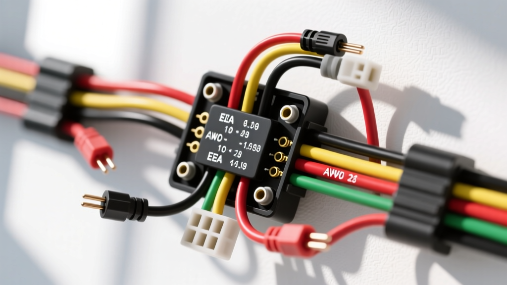
Introduction to the Car Radio Wiring Harness
Upgrading your vehicle's audio system is one of the most rewarding DIY automotive projects, but it requires a solid understanding of automotive electrical fundamentals. When searching for a wiring harness car radio diagram, beginners often feel overwhelmed by the maze of multicolored copper strands. A wiring harness serves as the critical bridge between your vehicle's factory electrical system and an aftermarket head unit, allowing you to retain OEM integrity without cutting or splicing factory wires.
Modern vehicles utilize complex multiplexed data networks, making the correct harness adapter just as important as the stereo itself. This guide breaks down the foundational elements of car radio wiring harnesses, including standard color codes, wire gauge specifications, and professional termination techniques endorsed by mobile electronics experts.
Standard EIA/CTA Aftermarket Wire Color Codes
The Consumer Technology Association (CTA), formerly the Electronic Industries Alliance (EIA), established a universal color-code standard for aftermarket car audio head units. Understanding these colors is mandatory for any 12V automotive electrical technician. Below is the definitive reference chart for standard aftermarket harnesses.
| Wire Color | Function | Standard AWG | Technical Notes |
|---|---|---|---|
| Yellow | 12V Constant (Memory) | 18 AWG | Connects directly to the battery. Maintains radio presets and clock memory. Must be fused within 18 inches of the power source. |
| Red | 12V Switched (Ignition) | 18 AWG | Receives power only when the ignition is in the ACC or ON position. Triggers the head unit to power up. |
| Black | Chassis Ground | 18 AWG | Must be terminated to a bare, unpainted metal surface on the chassis. Never ground to a factory wire. |
| Blue | Power Antenna | 18 AWG | Outputs 12V only when the AM/FM tuner is active. Drops to 0V when switching to CD or Aux. |
| Blue/White Stripe | Amplifier Turn-On | 18 AWG | Outputs 12V whenever the head unit is powered on. Used to trigger external amplifiers and DSPs. |
| Orange | Illumination / Dimmer | 22 AWG | Dims the head unit display when headlights are turned on. Often requires a resistor or CAN-bus module in modern cars. |
| White / White-Black | Front Left Speaker (+/-) | 18 AWG | The solid color is positive; the black-striped wire is negative (ground reference). |
| Gray / Gray-Black | Front Right Speaker (+/-) | 18 AWG | Ensure correct phase alignment to prevent acoustic cancellation. |
| Green / Green-Black | Rear Left Speaker (+/-) | 18 AWG | Do not ground the negative speaker wires to the chassis; they are bridged outputs on most modern IC amplifiers. |
| Purple / Purple-Black | Rear Right Speaker (+/-) | 18 AWG | Keep speaker wires separated from RCA interconnects to prevent electromagnetic interference (EMI). |
Understanding ISO 10487 Standard Pinouts
While aftermarket radios use the EIA color codes, the physical connector that plugs into the back of the radio often adheres to the ISO 10487 standard. This standard defines two primary 8-pin blocks: Block A (Power) and Block B (Speakers).
ISO Block A (Power Connector)
- Pin 4: 12V Constant (Yellow)
- Pin 7: 12V Switched (Red)
- Pin 8: Chassis Ground (Black)
- Pin 5: Illumination (Orange)
- Pin 1: Speed Pulse (Optional)
- Pin 2: Mute Control (Optional)
ISO Block B (Speaker Connector)
- Pin 1 & 2: Front Left (+ / -)
- Pin 3 & 6: Front Right (+ / -)
- Pin 5 & 8: Rear Left (+ / -)
- Pin 4 & 7: Rear Right (+ / -)
Note: Always verify pinouts with a digital multimeter (DMM) before applying power, as some manufacturers swap Pin 4 and Pin 7, which will cause the radio to lose memory every time the vehicle is turned off.
Wire Gauges (AWG) and Automotive Insulation Standards
Wire gauge is a critical factor in harness design. The American Wire Gauge (AWG) system dictates the current-carrying capacity of the copper conductor. For a standard 50W x 4 internal amplifier head unit, the maximum current draw rarely exceeds 10 to 12 amps. Therefore, 18 AWG wire is the industry standard for power, ground, and speaker outputs. High-current accessory wires (like main amp power) require 8 AWG to 4 AWG, while low-current data or trigger wires utilize 22 AWG.
Beyond gauge, the insulation jacket is paramount. According to the SAE J1128 standard for Low Tension Primary Cable, automotive wire must withstand extreme under-dash temperatures, abrasion, and chemical exposure. Professional harness builders use TXL (Thin-wall cross-linked) or GXL (General-purpose cross-linked) insulation. These materials are rated for continuous operation at 125°C to 155°C, vastly outperforming standard PVC wire, which melts and shorts out under high thermal loads.
OEM Adapter Harnesses and CAN-Bus Integration
You should never cut a vehicle's factory wiring harness. Instead, professionals use OEM-to-Aftermarket adapter harnesses (manufactured by brands like Metra, Scosche, or PAC). These adapters plug directly into the vehicle's factory radio plug and present standard EIA-colored bare wires on the other end.
The Challenge of Modern Data Networks
In vehicles manufactured after 2010, the factory radio is often integrated into the vehicle's CAN-bus (Controller Area Network) or GMLAN data network. In these applications, the 12V switched ignition signal is not a physical wire; it is a digital command sent over a twisted-pair data line. To install an aftermarket radio in these vehicles, you must use a data retention module (such as the Axxess ASWC-1, Maestro RR, or PAC RP4 series). These modules intercept the CAN-bus data, translate the digital ignition command, and output a physical 12V analog signal to the aftermarket radio's Red wire, while also retaining steering wheel controls and factory backup camera feeds.
Professional Wire Termination Techniques
The most common cause of automotive electrical failure is poor wire termination. As emphasized by the Mobile Electronics Certification Program (MECP), proper connection methods ensure low resistance and prevent galvanic corrosion.
- Heat Shrink Butt Connectors: Use nylon-insulated, marine-grade heat shrink butt connectors (sized for 22-18 AWG). Crimp the copper barrel with a ratcheting crimper, then apply heat until the internal adhesive sealant melts, creating a waterproof, airtight bond.
- Posi-Products: These twist-and-lock mechanical connectors are excellent for beginners. They feature a brass insert that bites into the copper strands, providing a high-tensile, low-resistance connection without the need for crimping tools.
- Soldering: While soldering creates a perfect metallurgical bond, it can make the wire stiff and prone to fatigue cracking in high-vibration environments. If you solder, always use rosin-core solder and cover the joint with adhesive-lined heat shrink tubing.
Critical Warning: Never use "T-taps" or "Scotch Locks." These devices pierce the wire insulation, exposing the raw copper to moisture and oxygen. This leads to rapid galvanic corrosion, high resistance, and eventual failure of the circuit.
Troubleshooting Common Harness Mistakes
Even with the correct wiring harness car radio adapter, beginners frequently encounter specific electrical anomalies. Use this diagnostic guide to resolve them:
1. Radio Loses Memory When Ignition is Turned Off
- Cause: The Yellow (Constant 12V) and Red (Switched 12V) wires are swapped.
- Fix: Use a multimeter to identify the always-hot and ignition-switched wires on the vehicle side of the adapter harness. Re-pin or re-crimp the connections accordingly.
2. Alternator Whine Through the Speakers
- Cause: A ground loop caused by high resistance on the Black ground wire, or grounding the head unit to a painted surface.
- Fix: Sand the chassis ground point down to bare, shiny metal. Ensure the ground wire is under 18 inches long and secured with a stainless steel ring terminal and machine screw.
3. Weak Bass and Hollow Sound
- Cause: Speakers are "out of phase," meaning the positive and negative wires on one or more speakers are reversed.
- Fix: Verify that the solid EIA color (e.g., White) connects to the speaker's positive terminal, and the black-striped wire (e.g., White/Black) connects to the negative terminal across all channels.
Conclusion
Mastering the fundamentals of car radio wiring harnesses transforms a frustrating installation into a seamless upgrade. By adhering to EIA color codes, respecting SAE J1128 wire insulation standards, and utilizing professional termination methods, you ensure your audio system operates reliably for the lifespan of the vehicle. Always consult the Consumer Technology Association (CTA) guidelines and vehicle-specific pinout diagrams before applying power to any new harness configuration.