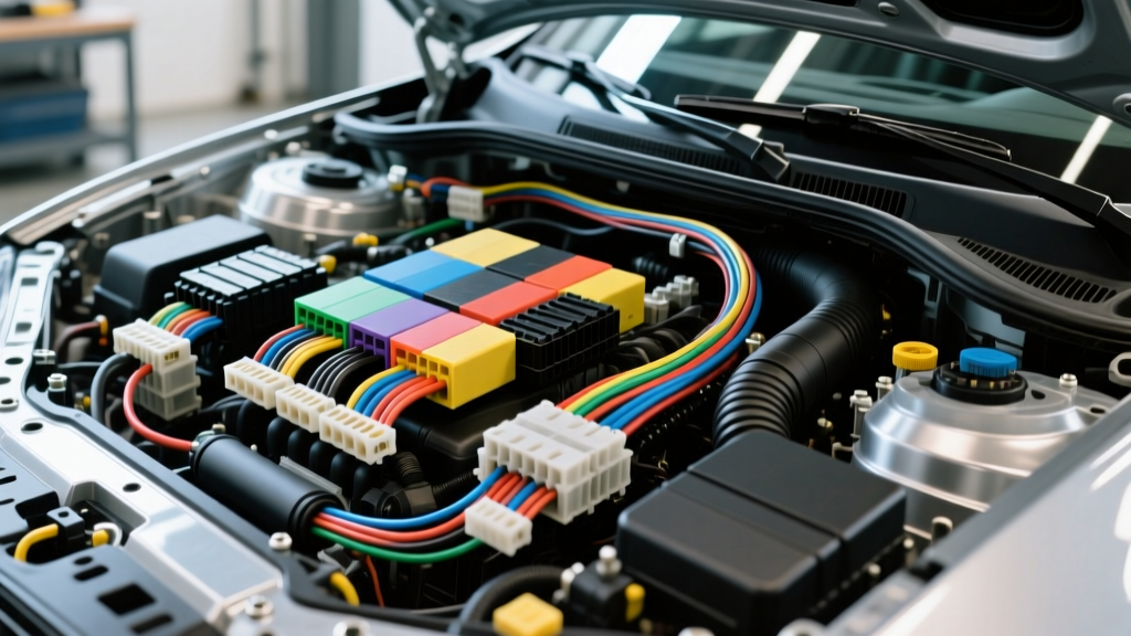
Introduction to Automotive Wiring Harness Architecture
When analyzing factory schematics or planning a custom engine swap, treating a vehicle's electrical system as a single, continuous loom is a fundamental mistake. Modern vehicles utilize a segmented network architecture. Understanding the distinct types of wiring harness in car platforms is critical for accurate diagnostics, efficient troubleshooting, and custom fabrication. Each harness segment is engineered for specific thermal, mechanical, and electrical demands, utilizing different wire insulation types, connector families, and gauge specifications. In this complete wiring diagram walkthrough, we will dissect the primary harness categories, trace specific OEM circuit paths, and decode the schematic designators used by automotive engineers.
The Core Types of Wiring Harness in Car Platforms
Automotive manufacturers divide the electrical system into distinct sub-harnesses to simplify assembly, reduce weight, and isolate high-noise circuits from sensitive data lines. Below is a breakdown of the primary harness types you will encounter on a master wiring diagram.
1. The Engine Bay Harness (EFI and Ignition)
The engine harness operates in the harshest environment, subjected to extreme heat, vibration, and exposure to hydrocarbons. Diagrams for this harness will specify high-temperature cross-linked polyethylene (XLPE) insulation, typically TXL or SXL wire rated for 125°C to 150°C, as outlined by SAE J1128 standards. Connectors here are predominantly sealed Metri-Pack 150 and 280 series with secondary silicone wedge locks. You will find heavy 10 AWG to 8 AWG feeds for the alternator and fuel pump, alongside 20 AWG to 22 AWG shielded wires for crankshaft and camshaft position sensors to prevent electromagnetic interference (EMI) from the ignition coils.
2. The Chassis and Body Harness
The chassis harness routes through the frame rails and undercarriage, connecting ABS modules, traction control sensors, and exterior lighting. Because it is exposed to water, road salt, and debris, this harness relies heavily on heavy-duty Deutsch DT or AMP Superseal connectors. Wire gauges here are generally thicker; headlight circuits often utilize 14 AWG or 12 AWG GXL wire to prevent voltage drop over the long run from the front fuse block to the rear tail lamps. CAN-bus lines for the ABS module will be clearly marked on diagrams as twisted pairs (typically 20 AWG), requiring 3 to 4 twists per inch to cancel out induced noise.
3. The Dashboard and Instrument Cluster Harness
Inside the cabin, thermal and moisture resistance takes a backseat to flexibility and space-saving. The dash harness uses thin-wall GXL or AVSS wire, often in 22 AWG to 24 AWG gauges, to bundle hundreds of circuits into tight conduit pathways behind the instrument panel. Connectors are mostly unsealed, high-cavity density Molex or Yazaki multi-port blocks. When reading the dash diagram, you will notice a high concentration of multiplexed data lines (LIN and CAN bus) communicating with the Body Control Module (BCM), replacing the heavy copper runs of older vehicles.
4. Transmission and Drivetrain Control Harnesses
Often integrated with the engine harness or routed along the transmission tunnel, this segment connects the Powertrain Control Module (PCM) to the Transmission Control Module (TCM) and internal shift solenoids. Modern 8-speed and 10-speed automatic transmissions utilize internal lead-frames and high-temperature Teflon-insulated wires to survive the 100°C+ environment of hot transmission fluid.
Diagram Walkthrough: Tracing a Gen IV LS Engine Harness
To understand how these types of wiring harness in car systems interact, let us walk through a standard General Motors Gen IV 5.3L/6.0L LS engine swap harness diagram, focusing on the Powertrain Control Module (PCM) E38/E40 integration.
The PCM is the nerve center, utilizing three primary connectors: X1 (Black, 38-pin), X2 (Grey, 38-pin), and X3 (Black, 38-pin) on later E40 models, or C1/C2 80-pin blocks on earlier E38 setups. When tracing the ignition circuit on the schematic, locate the Ignition 1 (IGN 1) feed. This is typically a 12 AWG Pink wire that provides switched 12V to the PCM, fuel injectors, and ignition coils. The diagram will show this circuit originating from the underhood fuse block, passing through a 20A fuse, and splicing into multiple branches.
Grounding is where most swap harnesses fail. The diagram will designate specific ground points (e.g., G101, G102) for the PCM. Pin X1-12 and X1-13 (Black/White wires) must be grounded directly to the engine cylinder head. A diagram note will often specify that this ground must be within 18 inches of the PCM to ensure a clean logic ground for the 5V reference sensors. Never rely on the chassis for PCM logic grounds; always trace the wire back to the engine block as dictated by the schematic.
Wire Gauge and Color Code Specification Chart
Reference this chart when verifying circuits against a factory diagram for a standard V8 EFI engine harness. Note that OEM colors may feature a primary color with a tracer (stripe).
| Circuit Function | Wire Color | AWG Size | Connector Cavity | Insulation Type |
|---|---|---|---|---|
| PCM Constant Battery | Red | 10 AWG | X1-20 | TXL (125°C) |
| PCM Switched Ignition | Pink | 12 AWG | X1-11 | TXL (125°C) |
| CAN Bus High (HS CAN) | Dark Green | 20 AWG | X2-14 | GXL / Shielded |
| CAN Bus Low (HS CAN) | Light Green | 20 AWG | X2-15 | GXL / Shielded |
| Injector 1 Control | Brown/White | 18 AWG | X1-34 | TXL (125°C) |
| MAP Sensor 5V Ref | Light Blue | 20 AWG | X2-22 | TXL (125°C) |
Decoding Splice Packs and Ground Distribution Blocks
A major hurdle when reading OEM wiring diagrams is deciphering the hidden junctions. You will frequently see designators like SP205 (Splice Pack 205) or G302 (Ground 302). A Splice Pack is a physical, sealed brass crimp barrel where multiple wires of the same circuit (e.g., the 12V IGN feed) are joined without using a bulky connector block. On the diagram, it looks like a simple node, but in the physical harness, it is a thick, taped bulge. When troubleshooting a dead circuit that shares a fuse with working components, the SP is your primary suspect for corrosion or a broken crimp.
Ground designators (G) indicate where a circuit terminates to bare metal. The schematic will list the physical location (e.g., 'Left Rear Frame Rail'). When performing a voltage drop test, you must measure from the component's ground pin to the battery negative terminal. A reading above 0.1V on a 12V circuit indicates high resistance at the G-point, usually due to paint, rust, or a loose star washer.
Connector Terminal Crimping and Weather Seals
Building or repairing any of the types of wiring harness in car applications requires strict adherence to terminal crimping standards. Automotive connectors like the Delphi Metri-Pack or TE Connectivity AMP Superseal utilize open-barrel terminals. The crimp must capture both the wire strands (conductor crimp) and the wire insulation (insulation crimp) to provide strain relief. Furthermore, weather-pack seals must be slid onto the wire before crimping. The seal must sit flush against the insulation crimp barrel. If the seal is pushed too far back, the connector will not lock into the plastic housing cavity; if pushed too far forward, it will interfere with the mating terminal pin, causing an open circuit.
Common Failure Modes in Segmented Harnesses
Understanding the harness type helps predict its failure mode. Engine harnesses frequently suffer from capillary action wicking, where oil or coolant breaches a sensor connector and travels up the wire strands under the insulation, eventually shorting out the PCM. Chassis harnesses typically fail due to abrasion against the frame or subframe, especially near suspension pick-up points where the harness flexes during suspension travel. Dash harnesses rarely suffer from environmental damage but are prone to terminal fretting corrosion due to the micro-vibrations of the cabin and the use of low normal-force unsealed terminals. Always apply dielectric grease to under-hood and chassis connectors to prevent moisture ingress and terminal oxidation.
Authoritative References
- SAE International - J1128: Low Tension Primary Cable (Reference for automotive wire insulation types and temperature ratings).
- TE Connectivity - Automotive Connector Systems (Technical data on terminal crimp profiles and sealed connector cavities).
- OEM Service Information Systems (e.g., GM Service Information) for factory schematic symbols, splice pack locations, and ground distribution charts.