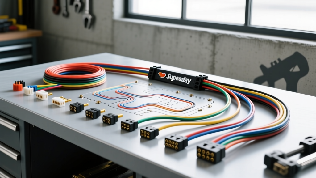
Upgrading to a Speedway Motors Wiring Harness: The 22-Circuit Solution
When transforming a classic chassis into a reliable street rod or restomod, the electrical system is often the most daunting hurdle. Decades-old OEM wiring is typically brittle, undersized for modern accessories, and lacks the circuit protection required for high-draw components. Selecting the right Speedway Motors wiring harness for your project bridges the gap between vintage aesthetics and modern reliability. The 22-circuit universal harness is the gold standard for hot rods, classic trucks, and pro-touring builds, providing dedicated, fused pathways for everything from electronic fuel injection (EFI) controllers to LED lighting arrays.
Unlike factory harnesses designed for a specific unibody stamping, a universal harness requires meticulous planning, precise bulkhead routing, and a solid understanding of automotive electrical architecture. This guide details the exact installation methodology, AWG specifications, and relay integration strategies necessary to execute a flawless upgrade using a Speedway Motors 22-circuit kit.
Pre-Installation: Fuse Block Placement and Circuit Mapping
Before cutting a single zip tie, you must determine the fuse block location. In a street rod application, under-dash mounting on the driver’s side is common, but it poses a severe safety risk if placed near the steering column or the driver’s left knee. The optimal location is typically under the passenger side dash, tucked above the glovebox, or mounted vertically on the passenger side kick panel. This keeps the bulkhead pass-through direct while protecting the fused circuits from accidental impact.
The Speedway Motors 22-circuit harness utilizes an EZ-fit fuse block with pre-terminated bulkhead connectors. Understanding the color-coded circuit mapping is critical for matching the harness to your vehicle’s specific switches and accessories.
| Circuit Function | Wire Color | AWG Size | Recommended Fuse | Connector Type |
|---|---|---|---|---|
| Headlights (Low Beam) | Yellow | 10 AWG | 20A ATO | Metri-Pack 280 |
| Headlights (High Beam) | Green | 10 AWG | 20A ATO | Metri-Pack 280 |
| Ignition Switch (Run/Start) | Purple | 12 AWG | 15A ATO | Ring Terminal |
| Turn Signals (Front/Rear) | Light Green (L) / Brown (R) | 14 AWG | 10A ATO | Weather-Pack |
| Brake Light Switch | White | 14 AWG | 15A ATO | Spade / Pigtail |
| Dash Illumination / Gauges | Gray | 14 AWG | 5A ATO | Micro-Pack |
| EFI / Fuel Pump Relay Trigger | Orange | 12 AWG | 20A ATO | Deutsch DT |
Note: Always verify wire functions against the specific schematic included in your Speedway kit, as color codes can vary slightly between the 22-circuit and 9-circuit variants.
Bulkhead Routing and Firewall Pass-Through
The transition from the engine bay to the passenger compartment is the most common failure point in custom wiring. The Speedway harness features a heavy-duty, pre-molded bulkhead connector designed to pass through a 4.5-inch by 2.5-inch oval firewall hole. Never route bare wires directly through sheet metal; vibration will inevitably shear the copper strands, leading to intermittent shorts or catastrophic fires.
Step-by-Step Firewall Pass-Through
- Template and Drill: Use the provided cardboard template to mark the firewall. Ensure the location is clear of the steering shaft, brake booster pushrod, and HVAC plumbing.
- Deburr and Paint: File the stamped steel edge smooth and apply cold galvanizing compound or chassis paint to prevent rust creep.
- Grommet Seating: Lubricate the heavy rubber bulkhead grommet with a silicone-based dielectric grease (such as Permatex 22058). This prevents the rubber from tearing and ensures a watertight seal against the firewall.
- Weatherproofing: Once the connector is mated inside the cabin, apply a bead of RTV silicone around the exterior flange to prevent water intrusion during heavy rain or car washes.
Relay Integration for High-Draw Upgrades
A universal harness provides the trigger circuits for high-draw accessories, but it should never carry the primary load for components like halogen headlights, dual Spal cooling fans, or high-pressure fuel pumps. According to Bosch Automotive Electrics guidelines, any circuit exceeding 10 amps continuously should be managed by a relay to prevent voltage drop and switch degradation.
Headlight Relay Wiring Logic
Instead of routing the 10 AWG Yellow and Green headlight wires directly to the headlight buckets, use them to trigger the coil side of two standard 4-pin ISO mini relays (Bosch style).
- Pin 85 (Coil Ground): Connect to a clean, dedicated chassis ground.
- Pin 86 (Coil Trigger): Connect to the harness Yellow (Low) or Green (High) wire.
- Pin 30 (Load Power): Connect directly to the battery positive via a dedicated 30A Maxi-fuse and 10 AWG feed wire.
- Pin 87 (Load Output): Route to the headlight bulb connector.
This configuration ensures the headlight dimmer switch only handles the milliamp draw of the relay coils, drastically extending the life of vintage column switches and delivering full battery voltage to the bulbs.
Terminal Crimping vs. Soldering: The SAE Standard
A pervasive myth in the hot rod community is that soldering wire connections is superior to crimping. In high-vibration automotive environments, this is entirely false. The SAE J1128 Standard for low-tension primary cable and terminal interfaces heavily favors mechanical crimping. When solder wicks into the copper strands beneath the insulation, it creates a rigid, brittle point. Under engine harmonics and chassis flex, this stiff section acts as a fulcrum, causing the copper strands to snap just outside the solder joint.
For all field terminations on your Speedway harness, use a ratcheting crimp tool calibrated for Metri-Pack or Weather-Pack terminals. Follow the crimp with dual-wall, adhesive-lined heat shrink. The inner layer of thermoplastic adhesive melts and flows into the wire strands, creating a waterproof seal that prevents capillary action from drawing moisture under the wire insulation.
Grounding Architecture: Avoiding the Floating Ground
The most frequent cause of erratic gauge behavior, dim headlights, and EFI stalling in street rods is a poor ground strategy. Relying on rusty chassis steel, painted engine blocks, or hinge bolts for ground returns is a recipe for disaster. A proper ground system requires a dedicated, star-configured architecture.
- Battery to Chassis: Use a minimum 1/0 AWG copper cable from the negative battery post to a clean, bare-metal point on the chassis frame rail.
- Engine to Chassis: The engine is isolated by rubber motor mounts. You must install a braided copper ground strap (minimum 2 AWG) from the cylinder head or intake manifold directly to the chassis. Never use aluminum straps, as they are prone to galvanic corrosion and possess higher electrical resistance.
- Centralized Ground Bus: For interior accessories (gauges, radio, glovebox light), install a brass or copper ground bus bar under the dash. Run a single 8 AWG ground wire from this bus bar through the bulkhead to the chassis, and terminate all interior accessory grounds to the bus bar using star washers to bite through any paint or powdercoat.
Troubleshooting: Voltage Drop Testing
If a component powered by the Speedway harness is underperforming (e.g., a fuel pump humming weakly or headlights glowing yellow), do not immediately replace the component. Perform a voltage drop test. Set your digital multimeter to DC Volts. Place the red probe on the positive battery terminal and the black probe on the positive terminal of the load (e.g., the fuel pump). With the circuit active, a reading above 0.2V indicates excessive resistance in the supply wire, a corroded bulkhead pin, or an undersized fuse holder. Repeat the test on the ground side (red probe on load ground, black probe on battery negative). Identifying voltage drop is the hallmark of a professional automotive electrician and ensures your restomod operates flawlessly on the street.
For further technical documentation on universal harness routing and switch pinouts, consult the Speedway Motors Tech Guides to verify specific bulkhead pin assignments for your exact kit generation.